


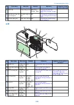


5. Remove the Low Voltage Unit [1]
• 3 connectors [2]
[1]
[2]
3x
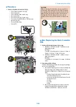
Removing the Fixing Sub PCB
■ Preparation
1. Removing the Right Cover.(Refer to
)
2. Removing the Controller Cover.(Refer to
the Controller Cover” on page 157
)
3. Removing the Wireless LAN PCB.(MF728Cdw /
727Cdw / 724Cdw only) (Refer to
Wireless LAN PCB (MF728Cdw / 727Cdw / 724Cdw)”
on page 157
)
4. Removing the Main Controller PCB.(Refer to
“Removing the Main Controller PCB” on page 157
5. Removing the Main Controller Support Plate.(Refer
“Removing the Main Controller Support Plate” on
6. Removing the FAX PCB.(MF728Cdw / 727Cdw /
725Cdn only) (Refer to
(MF728Cdw / 727Cdw / 725Cdw)” on page 171
7. Removing the Fixing/Fixing Power Supply Cooling
Power Supply Cooling Fan Unit” on page 180
■ Procedure
1. Remove the PCB Fixation Plate [1] (FAX model only).
• 2 Screws [2]
[1]
[2]
2x
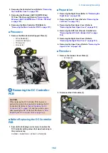
2. Remove the wire harness [1], and remove the wire
harness guide [2].
• 3 connectors [3]
• 4 fixing guides [4]
• 1 claw [5]
[2]
[5]
[3]
[3]
[1]
[4]
4x
1x
3x
4. Disassembly/Assembly
166
Summary of Contents for MF720 Series
Page 1: ...Revision 2 0 MF720 Series Service Manual...
Page 12: ...Product Overview 1 Product Lineups 5 Product Features 7 Specifications 8 Name of Parts 14...
Page 79: ...4 Click Import Export Import 1 2 2 Technical Explanation 71...
Page 103: ...Durable Parts No durable parts is set for this product 3 Periodical Service 95...
Page 104: ...Periodical Services No periodical service is set for this product 3 Periodical Service 96...
Page 232: ...Adjustment 5 Overview 225 Adjustment at Parts Replacement 226...
Page 248: ...Troubleshooting 6 Test Print 241 Trouble shooting items 243 Version Upgrade 244 Debug Log 248...
Page 258: ...Error Jam Alarm 7 Outline 251 Error Codes 252 Jam Code 257...
Page 267: ...Service Mode 8 Overview 260 COPIER 264 FEEDER 300 FAX 302 TESTMODE 308...
Page 322: ...APPENDICES Service Tools 315 General Circuit Diagram 316 Print Sequence 317 Backup Data 318...