


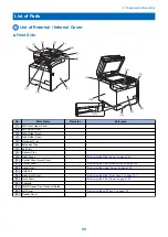


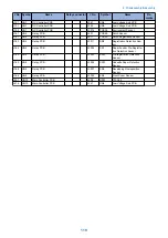


J No. Symbol
Name
Relay connector
J No.
Symbol
Name
Remarks
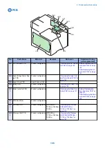
J929 UN13
Main Controller PCB
J392
SW1
Main Power Switch
MF728Cdw /
724Cdw
J918 UN13
Main Controller PCB
J941
UN16
FAX-NCU PCB
MF728Cdw /
727Cdw /
726Cdw /
725Cdn
J921
1
UN13
Main Controller PCB
J2009
UN17
Off Hook PCB
MF728Cdw /
727Cdw /
726Cdw /
725Cdn
J942 UN16
FAX-NCU PCB
J2001
UN17
Off Hook PCB
MF728Cdw /
727Cdw /
726Cdw /
725Cdn
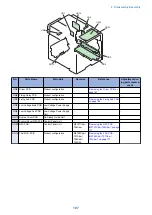
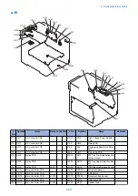
■ 2/5
J3015
J3011
J611
J3001
J3005
J3002
J3003
J3004
J901
J601
J912
J915
J914
J166
J163
J164
J362
J153
J151
J130
J409
J165
J351
J361
J352
J161
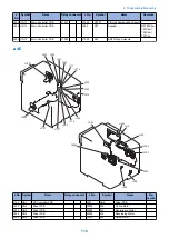
J No. Symbol
Name
Relay connector
J No.
Symbol
Name
Re-
marks
J130
UN1
DC Controller PCB
J912
UN13
Main Controller PCB
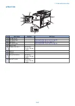
4. Disassembly/Assembly
109
Summary of Contents for MF720 Series
Page 1: ...Revision 2 0 MF720 Series Service Manual...
Page 12: ...Product Overview 1 Product Lineups 5 Product Features 7 Specifications 8 Name of Parts 14...
Page 79: ...4 Click Import Export Import 1 2 2 Technical Explanation 71...
Page 103: ...Durable Parts No durable parts is set for this product 3 Periodical Service 95...
Page 104: ...Periodical Services No periodical service is set for this product 3 Periodical Service 96...
Page 232: ...Adjustment 5 Overview 225 Adjustment at Parts Replacement 226...
Page 248: ...Troubleshooting 6 Test Print 241 Trouble shooting items 243 Version Upgrade 244 Debug Log 248...
Page 258: ...Error Jam Alarm 7 Outline 251 Error Codes 252 Jam Code 257...
Page 267: ...Service Mode 8 Overview 260 COPIER 264 FEEDER 300 FAX 302 TESTMODE 308...
Page 322: ...APPENDICES Service Tools 315 General Circuit Diagram 316 Print Sequence 317 Backup Data 318...