
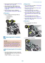


7. Remove the DC Controller Support Plate [1].
• 1 Special Flat-head Screw [2]
• 2 Black Screws [3]
• 3 Screws [4]
• 2 Bosses [5]
• 1 Protrusion [6]
CAUTION:
Since the Special Flat-head Screw [2] adjusts the
interval between the plate [1] and parts in the vicinity,
be sure to install the Special Flat-head Screw [2] in the
location it was in before removal.
[2]
[4]
[3]
[1]
[5]
[5]
[6]
[3]
[4]
6x
CAUTION:
When installing, be sure to place the [A] part of DC
Controller Support Plate under the [B] part of the
Harness Guide.
[A]
[B]
8. Remove the Main Switch Unit [1].
• 2 Screws [2]
• 1 Hook [3]
• 1 Reuse Band [4]
[2]
[1]
[1]
[3]
[4]
2x
1x
9. Remove the Main Switch Unit Connecting Plate [1].
• 3 Screws [2]
[1]
[2]
[2]
3x
4. Disassembly/Assembly
175
Summary of Contents for MF720 Series
Page 1: ...Revision 2 0 MF720 Series Service Manual...
Page 12: ...Product Overview 1 Product Lineups 5 Product Features 7 Specifications 8 Name of Parts 14...
Page 79: ...4 Click Import Export Import 1 2 2 Technical Explanation 71...
Page 103: ...Durable Parts No durable parts is set for this product 3 Periodical Service 95...
Page 104: ...Periodical Services No periodical service is set for this product 3 Periodical Service 96...
Page 232: ...Adjustment 5 Overview 225 Adjustment at Parts Replacement 226...
Page 248: ...Troubleshooting 6 Test Print 241 Trouble shooting items 243 Version Upgrade 244 Debug Log 248...
Page 258: ...Error Jam Alarm 7 Outline 251 Error Codes 252 Jam Code 257...
Page 267: ...Service Mode 8 Overview 260 COPIER 264 FEEDER 300 FAX 302 TESTMODE 308...
Page 322: ...APPENDICES Service Tools 315 General Circuit Diagram 316 Print Sequence 317 Backup Data 318...