


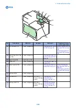


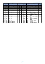


J No. Symbol
Name
Relay connector
J No.
Symbol
Name
Re-
marks
J151
UN1
DC Controller PCB
J361
UN9
Low Voltage Sub PCB
J151
UN1
DC Controller PCB
J362
UN9
Low Voltage Sub PCB
J153
UN1
DC Controller PCB
J3015
PCB28
Environment Sensor
J161
UN5
Relay PCB
J601
PCB29
Patch Sensor
J161
UN5
Relay PCB
J611
PCB30
Patch Registration Sensor
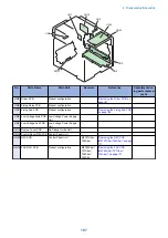
J163
UN5
Relay PCB
J3011
SR4
Registration Detection Sen-
sor
J164
UN5
Relay PCB
J3002
SR1
Paper Feeder Pre-Registra-
tion Detection Sensor
J165
UN5
Relay PCB
J3003
SR12
Pre-registration Detection
Sensor
J165
UN5
Relay PCB
J3004
SR13
Cassette Paper Detection
Sensor
J166
UN5
Relay PCB
J3001
SR6
Developing Homeposition
Sensor
J166
UN5
Relay PCB
J3005
SR2
Front Cover Sensor
J901
UN13
Main Controller PCB
J409
UN12
CIS Unit
J914
UN13
Main Controller PCB
J351
UN9
Low Voltage Sub PCB
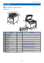
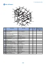
4. Disassembly/Assembly
110
Summary of Contents for MF720 Series
Page 1: ...Revision 2 0 MF720 Series Service Manual...
Page 12: ...Product Overview 1 Product Lineups 5 Product Features 7 Specifications 8 Name of Parts 14...
Page 79: ...4 Click Import Export Import 1 2 2 Technical Explanation 71...
Page 103: ...Durable Parts No durable parts is set for this product 3 Periodical Service 95...
Page 104: ...Periodical Services No periodical service is set for this product 3 Periodical Service 96...
Page 232: ...Adjustment 5 Overview 225 Adjustment at Parts Replacement 226...
Page 248: ...Troubleshooting 6 Test Print 241 Trouble shooting items 243 Version Upgrade 244 Debug Log 248...
Page 258: ...Error Jam Alarm 7 Outline 251 Error Codes 252 Jam Code 257...
Page 267: ...Service Mode 8 Overview 260 COPIER 264 FEEDER 300 FAX 302 TESTMODE 308...
Page 322: ...APPENDICES Service Tools 315 General Circuit Diagram 316 Print Sequence 317 Backup Data 318...