


2. Printing temperature control
This controls the fixing film temperature during printing to maintain the target.
Different temperatures are set in the fixing film depending on paper types.
3. Sheet-to-sheet temperature control
This control lowers the sheet-to-sheet fixing heater temperature during continuous printing in the low-speed mode to prevent
temperature rise on the pressure roller.
Different sheet-to-sheet temperatures are set depending on sheet intervals or paper types.
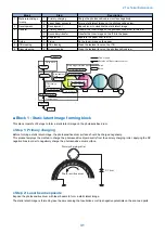
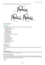
■ Protective Control
his control is to detect abnormal temperature rise in the fixing assembly to shut off power supply to the fixing heater.
This product has the following 3 protective controls to prevent abnormal temperature rise in the fixing assembly.
• DC controller
• Fixing heater safety circuit
• Temperature fuse
The descriptions below are the details of each protective control.
1. DC controller
When DC Controller monitors temperature of the central thermistor of the fixing heater and exceeds the pre-defined
temperature, which is thought abnormally high temperature, therefore the drive signal (FSRD+, FSRD-) of the fixing heater
is stopped outputting and the relay is turned off and the power distribution to the heater is stopped.
2. Fixing heater safety circuit
This circuit detects abnormal temperatures in the center of the fixing heater to shut off power supply to the heater.
3. Temperature fuse
When the temperature of the fixing heater abnormally rises, the temperature fuse is open to shut off power supply to the
heater.
• 226 deg C or higher detected at the temperature fuse.
■ Failure detection
The DC controller determines failures of the fixing assembly under conditions below to stop the fixing heater drive signal output
(FSRD+, FSRD-) and shut off relay and power supply to the heater. At the same time, it notifies the failure occurrence to the main
controller.
1. Start-up failure detection
• The thermistor temperature does not exceed startup temperature 1 within the pre-defined time after start-up of the heater
from the waiting status.
• The thermistor temperature does not exceed startup temperature 2 within the pre-defined time after reaching startup
temperature 1 upon start-up of the heater from the waiting status.
• The thermistor temperature does not reach the target temperature within the pre-defined time after heater temperature
control during initial rotation.
[Related error code]
E000-0000
2. Abnormally high temperature failure
• The thermistor temperature remains at pre-defined temperature or higher for the pre-defined time.
[Related error code]
E001-0000 main thermistor
E001-0001 sub thermistor
3. Abnormally low temperature failure
• The thermistor temperature remains at pre-defined temperature or lower within the pre-defined time after heater
temperature control during printing.
[Related error code]
E003-0000 main thermistor
E003-0001 sub thermistor (MF8500 Series only)
4. Fixing heater drive circuit failure
• The zero-cross signal has not been detected for a certain times within the pre-defined time after power-ON.
• The zero-cross signal is detected after power-ON but has not been detected continuously within the pre-defined time
during printing.
[Related error code]
E004-0000
2. Technical Explanation
43
Summary of Contents for MF720 Series
Page 1: ...Revision 2 0 MF720 Series Service Manual...
Page 12: ...Product Overview 1 Product Lineups 5 Product Features 7 Specifications 8 Name of Parts 14...
Page 79: ...4 Click Import Export Import 1 2 2 Technical Explanation 71...
Page 103: ...Durable Parts No durable parts is set for this product 3 Periodical Service 95...
Page 104: ...Periodical Services No periodical service is set for this product 3 Periodical Service 96...
Page 232: ...Adjustment 5 Overview 225 Adjustment at Parts Replacement 226...
Page 248: ...Troubleshooting 6 Test Print 241 Trouble shooting items 243 Version Upgrade 244 Debug Log 248...
Page 258: ...Error Jam Alarm 7 Outline 251 Error Codes 252 Jam Code 257...
Page 267: ...Service Mode 8 Overview 260 COPIER 264 FEEDER 300 FAX 302 TESTMODE 308...
Page 322: ...APPENDICES Service Tools 315 General Circuit Diagram 316 Print Sequence 317 Backup Data 318...