

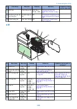


3. Remove the Fixing Sub PCB [1].
• 1 screw [2]
• 1 connector [3]
[1]
[2]
[3]
1x
1x
Removing the Driver PCB
■ Preparation
1. Removing the Right Cover.(Refer to
)
2. Removing the Left Cover.(Refer to
)
3. Removing the Right Front Cover.(Refer to
“Removing the Right Front Cover” on page 121
)
4. Removing the ADF Unit + Reader Unit.(Refer to
“Removing the ADF Unit + Reader Unit” on page
130
5. Removing the Rear Upper Cover.(Refer to
“Removing the Rear Upper Cover” on page 123
)
6. Removing the Upper Cover.(Refer to
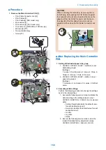
7. Removing the Wireless LAN PCB.(MF728Cdw /
727Cdw / 724Cdw only) (Refer to
Wireless LAN PCB (MF728Cdw / 727Cdw / 724Cdw)”
on page 157
)
8. Removing the Main Controller PCB.(Refer to
“Removing the Main Controller PCB” on page 157
9. Removing the Main Controller Support Plate.(Refer
“Removing the Main Controller Support Plate” on
■ Procedure
1. Remove the flat cable guide case [1].
• 1 screw [2]
• 2 claws [3]
[1]
[2]
[3]
[3]
1x
2x
4. Disassembly/Assembly
167
Summary of Contents for MF720 Series
Page 1: ...Revision 2 0 MF720 Series Service Manual...
Page 12: ...Product Overview 1 Product Lineups 5 Product Features 7 Specifications 8 Name of Parts 14...
Page 79: ...4 Click Import Export Import 1 2 2 Technical Explanation 71...
Page 103: ...Durable Parts No durable parts is set for this product 3 Periodical Service 95...
Page 104: ...Periodical Services No periodical service is set for this product 3 Periodical Service 96...
Page 232: ...Adjustment 5 Overview 225 Adjustment at Parts Replacement 226...
Page 248: ...Troubleshooting 6 Test Print 241 Trouble shooting items 243 Version Upgrade 244 Debug Log 248...
Page 258: ...Error Jam Alarm 7 Outline 251 Error Codes 252 Jam Code 257...
Page 267: ...Service Mode 8 Overview 260 COPIER 264 FEEDER 300 FAX 302 TESTMODE 308...
Page 322: ...APPENDICES Service Tools 315 General Circuit Diagram 316 Print Sequence 317 Backup Data 318...