Chapter 16
16-62
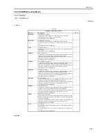
T-16-65
<FEEDER>
T-16-66
<JAM>
T-16-67
<MISC>
T-16-68
<PRDC-1>
T-16-69
COPIER > COUNTER > PICKUP
Sub-item
Description
Level
C1/2/3/4
cassette 1/2/3/4 pickup total counter
Indicates the number of sheets picked up from the cassette 1 (right deck)/2
(left deck)/3/4.
after 99999999, rests to 00000000
1
MF
manual feeder pickup total counter
Indicates the number of sheets picked up from the manual feed pickup unit.
after 99999999, resets to 00000000
1
DK
deck pickup total counter
Indicates the number of sheets picked up from the deck pickup unit.
after 99999999, ret to 00000000
1
2-SIDE
duplex pickup total counter
Indicates the number of sheets picked up for duplexing.
after 99999999, resets to 00000000.
1
COPIER > COUNTER > FEEDER
Sub-item
Description
Level
FEED
ADF original pick total counter
1
DFOP-CNT
Indicates the number of times the ADF hinge has opened/closed.
setting
0: OFF (default)
00000000 to 99999999
1
COPIER > COUNTER > JAM
Sub-item
Description
Level
TOTAL
total jam counter
1
FEEDER
feeder total jam counter
1
SORTER
finisher total jam counter
1
2-SIDE
duplexing unit jam counter
1
MF
manual feed pickup jam counter
1
C1/2/3/4
right deck/left deck/cassette 3/cassette 4 jam counter
1
DK
side paper deck jam counter
1
COPIER > COUNTER > MISC
Sub-item
Description
Level
FIX-WEB
fixing web counter (Be sure to reset the counter when the fixing web has been
replaced.)
1
WST-TNR
waste toner counter (Be sure to reset the counter when waste toner has been
disposed of.)
1
COPIER > COUNTER > PRDC-1
Sub-item
Description
Level
PRM-WIRE
primary charging wire counter
1
PRM-GRID
primary grid wire counter
1
PO-WIRE
pre-transfer charging wire counter
1
TR-WIRE
transfer charging wire counter
1
Summary of Contents for iR6570 series
Page 1: ...Mar 29 2005 Service Manual iR6570 5570 Series...
Page 2: ......
Page 6: ......
Page 26: ...Contents...
Page 27: ...Chapter 1 Introduction...
Page 28: ......
Page 30: ......
Page 55: ...Chapter 2 Installation...
Page 56: ......
Page 58: ...Contents 2 9 3 Mounting the Cassette Heater 2 34...
Page 98: ......
Page 99: ...Chapter 3 Basic Operation...
Page 100: ......
Page 102: ......
Page 110: ......
Page 111: ...Chapter 4 Main Controller...
Page 112: ......
Page 114: ......
Page 135: ...Chapter 5 Original Exposure System...
Page 136: ......
Page 181: ...Chapter 6 Laser Exposure...
Page 182: ......
Page 184: ......
Page 192: ......
Page 193: ...Chapter 7 Image Formation...
Page 194: ......
Page 198: ......
Page 259: ...Chapter 8 Pickup Feeding System...
Page 260: ......
Page 350: ......
Page 351: ...Chapter 9 Fixing System...
Page 352: ......
Page 401: ...Chapter 10 External and Controls...
Page 402: ......
Page 406: ......
Page 448: ......
Page 449: ...Chapter 11 MEAP...
Page 450: ......
Page 452: ......
Page 455: ...Chapter 12 Maintenance and Inspection...
Page 456: ......
Page 458: ......
Page 468: ......
Page 469: ...Chapter 13 Standards and Adjustments...
Page 470: ......
Page 505: ...Chapter 14 Correcting Faulty Images...
Page 506: ......
Page 508: ......
Page 537: ...Chapter 15 Self Diagnosis...
Page 538: ......
Page 540: ......
Page 565: ...Chapter 16 Service Mode...
Page 566: ......
Page 568: ......
Page 633: ...Chapter 17 Upgrading...
Page 634: ......
Page 636: ......
Page 641: ...Chapter 17 17 5 F 17 4 HDD Boot ROM Flash ROM System Software...
Page 646: ...Chapter 17 17 10 F 17 11 8 Click START F 17 12...
Page 675: ...Chapter 17 17 39 F 17 59 2 Select the data to download F 17 60 3 Click Start...
Page 677: ...Chapter 18 Service Tools...
Page 678: ......
Page 680: ......
Page 683: ...Mar 29 2005...
Page 684: ......


