Chapter 5
5-1
5.1 Construction
5.1.1 Specifications, Controls, and Functions
0008-7496
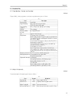
The specifications, controls, and functions of the machine's original exposure system are as follows:
T-5-1
5.1.2 Major Components
0008-7497
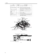
The major components of the original exposure system are as follows:
T-5-2
Item
Description
Scanning lamp
xenon lamp
Original scanning
book mode: by moving the scanner
ADF mode: by moving original
Original reading
resolution
600 x 600 dpi (main scanning x sub scanning)
Halftone
256 gradations
Scanning position
detection
by scanner HP sensor
lens
single-focal point, fixed type
Magnification
[1] in platen mode: 25% to 400%
main scanning direction: image processing by controller block
sub scanning direction: scanning speed variation (No. 1 mirror
base; 100% or higher)
in combination with image processing by reader block (50% or
higher and lower than 100%)
in combination with image processing in reader block and
controller block (lower than 50%)
[2] ADF mode: 25% to 200%
main scanning direction: image processing in controller block
sub scanning direction: original movement speed variation (50% or
higher); in combination with image processing in controller block (lower
than 50%)
Scanner drive control
No. 1/2 mirror base: control by pulse motor
Scanning lamp control [1]activation control by pulse motor
[2]error detection control
Original size detection [1]book mode
sub scanning direction: by reflection type sensor
main scanning direction: by CCD
[2] ADF mode
main scanning direction: by slide guide in ADF
sub scanning direction: by photosensor in ADF
Item
Notation
Description
Scanning lamp
LA1
xenon lamp (90,000 lx)
Scanner motor
M501
2-phase pulse motor (pulse control)
Reader Cooling fan
FM501
cools the reader block
ADF open/closed sensor 1
PS501
detects the state (open/closed) of the ADF; at 5 deg
Summary of Contents for iR6570 series
Page 1: ...Mar 29 2005 Service Manual iR6570 5570 Series...
Page 2: ......
Page 6: ......
Page 26: ...Contents...
Page 27: ...Chapter 1 Introduction...
Page 28: ......
Page 30: ......
Page 55: ...Chapter 2 Installation...
Page 56: ......
Page 58: ...Contents 2 9 3 Mounting the Cassette Heater 2 34...
Page 98: ......
Page 99: ...Chapter 3 Basic Operation...
Page 100: ......
Page 102: ......
Page 110: ......
Page 111: ...Chapter 4 Main Controller...
Page 112: ......
Page 114: ......
Page 135: ...Chapter 5 Original Exposure System...
Page 136: ......
Page 181: ...Chapter 6 Laser Exposure...
Page 182: ......
Page 184: ......
Page 192: ......
Page 193: ...Chapter 7 Image Formation...
Page 194: ......
Page 198: ......
Page 259: ...Chapter 8 Pickup Feeding System...
Page 260: ......
Page 350: ......
Page 351: ...Chapter 9 Fixing System...
Page 352: ......
Page 401: ...Chapter 10 External and Controls...
Page 402: ......
Page 406: ......
Page 448: ......
Page 449: ...Chapter 11 MEAP...
Page 450: ......
Page 452: ......
Page 455: ...Chapter 12 Maintenance and Inspection...
Page 456: ......
Page 458: ......
Page 468: ......
Page 469: ...Chapter 13 Standards and Adjustments...
Page 470: ......
Page 505: ...Chapter 14 Correcting Faulty Images...
Page 506: ......
Page 508: ......
Page 537: ...Chapter 15 Self Diagnosis...
Page 538: ......
Page 540: ......
Page 565: ...Chapter 16 Service Mode...
Page 566: ......
Page 568: ......
Page 633: ...Chapter 17 Upgrading...
Page 634: ......
Page 636: ......
Page 641: ...Chapter 17 17 5 F 17 4 HDD Boot ROM Flash ROM System Software...
Page 646: ...Chapter 17 17 10 F 17 11 8 Click START F 17 12...
Page 675: ...Chapter 17 17 39 F 17 59 2 Select the data to download F 17 60 3 Click Start...
Page 677: ...Chapter 18 Service Tools...
Page 678: ......
Page 680: ......
Page 683: ...Mar 29 2005...
Page 684: ......


