Chapter 5
5-6
5.3 Various Control
5.3.1 Controlling the Scanner Drive System
5.3.1.1 Overview
0008-7502
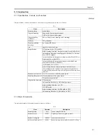
The following shows the components associated with the scanner drive system:
F-5-9
[1] Scanner Motor M501 Drive Signal
starts/stops the motor; controls the direction and speed of its rotation
[2] Scanner HP Detection Signal
detects the presence of the No. 1 mirror base at home position
5.3.1.2 Controlling the Scanner Motor
0008-7503
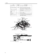
The configuration of the system used to control the scanner motor is as follows; the motor driver on the interface PCB operates according to the signals
from the CPU to start/stop the scanner motor and to control the direction and speed of its rotation
F-5-10
a. Reverse Movement After a Scan
After an image scan, the No. 1 mirror base is moved in reverse as far as the shading position at 234 mm/sec regardless of the selected magnification.
b. Forward Movement During a Scan
During an image scan, the No. 1 mirror base is controlled at the speed indicated in the following figure; the No. 1 mirror base is moved forward at 325
mm/sec for 100% magnification.
[1]
[2]
Reader
controller
PCB
Interface
PCB
(forward)
(reverse)
Scanner motor
Light-blocking plate
No.2 mirror
base
Scanning
lamp
No.1 mirror base
Scanner
HP sensor
Reader controller PCB
Motor
driver
Interface PCB
+24V/15V
J306
A
A*
B
B*
CPU
1
2
3
4
6
5
J308
J307
J202
J203
Scanner
motor
M501
[1]
[1] Scanner motor control signal
Summary of Contents for iR6570 series
Page 1: ...Mar 29 2005 Service Manual iR6570 5570 Series...
Page 2: ......
Page 6: ......
Page 26: ...Contents...
Page 27: ...Chapter 1 Introduction...
Page 28: ......
Page 30: ......
Page 55: ...Chapter 2 Installation...
Page 56: ......
Page 58: ...Contents 2 9 3 Mounting the Cassette Heater 2 34...
Page 98: ......
Page 99: ...Chapter 3 Basic Operation...
Page 100: ......
Page 102: ......
Page 110: ......
Page 111: ...Chapter 4 Main Controller...
Page 112: ......
Page 114: ......
Page 135: ...Chapter 5 Original Exposure System...
Page 136: ......
Page 181: ...Chapter 6 Laser Exposure...
Page 182: ......
Page 184: ......
Page 192: ......
Page 193: ...Chapter 7 Image Formation...
Page 194: ......
Page 198: ......
Page 259: ...Chapter 8 Pickup Feeding System...
Page 260: ......
Page 350: ......
Page 351: ...Chapter 9 Fixing System...
Page 352: ......
Page 401: ...Chapter 10 External and Controls...
Page 402: ......
Page 406: ......
Page 448: ......
Page 449: ...Chapter 11 MEAP...
Page 450: ......
Page 452: ......
Page 455: ...Chapter 12 Maintenance and Inspection...
Page 456: ......
Page 458: ......
Page 468: ......
Page 469: ...Chapter 13 Standards and Adjustments...
Page 470: ......
Page 505: ...Chapter 14 Correcting Faulty Images...
Page 506: ......
Page 508: ......
Page 537: ...Chapter 15 Self Diagnosis...
Page 538: ......
Page 540: ......
Page 565: ...Chapter 16 Service Mode...
Page 566: ......
Page 568: ......
Page 633: ...Chapter 17 Upgrading...
Page 634: ......
Page 636: ......
Page 641: ...Chapter 17 17 5 F 17 4 HDD Boot ROM Flash ROM System Software...
Page 646: ...Chapter 17 17 10 F 17 11 8 Click START F 17 12...
Page 675: ...Chapter 17 17 39 F 17 59 2 Select the data to download F 17 60 3 Click Start...
Page 677: ...Chapter 18 Service Tools...
Page 678: ......
Page 680: ......
Page 683: ...Mar 29 2005...
Page 684: ......

