Chapter 2
2-28
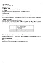
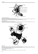
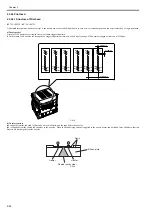
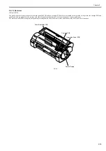
2.3.2.5.2 Structure of Purge Unit
0023-1476
iPF765 / iPF760 / iPF750 / iPF755
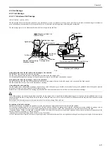
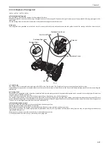
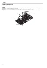
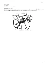
a) Cap unit
The cap unit is used to cap the printhead nozzles during capping and cleaning. The portion that touches the face plate is made from rubber. Two caps are arranged
for the printhead (six arrays of nozzles) installed in the carriage.
During cleaning, the caps used for both suction and capping are used to suck ink from the printhead using the suction pump.
During capping, the caps are raised by the purge motor to cover the printhead when the carriage has moved to the home position, thus protecting the nozzles.
F-2-18
Carriage Lock Pin
Wiper Blade
Glycerin Tank
Purge Motor
Pump Encoder Sensor
Pump Cam Sensor
Cap
Summary of Contents for iPF750 series
Page 1: ...Jul 25 2012 Service Manual iPF760 750 series ...
Page 2: ......
Page 6: ......
Page 11: ...Chapter 1 PRODUCT DESCRIPTION ...
Page 12: ......
Page 14: ...Contents 1 7 3 5 Self diagnostic Feature 1 71 1 7 3 6 Disposing of the Lithium Battery 1 72 ...
Page 87: ...Chapter 2 TECHNICAL REFERENCE ...
Page 88: ......
Page 99: ...Chapter 2 2 9 ...
Page 145: ...Chapter 3 INSTALLATION ...
Page 146: ......
Page 148: ......
Page 152: ......
Page 153: ...Chapter 4 DISASSEMBLY REASSEMBLY ...
Page 154: ......
Page 156: ......
Page 214: ...Chapter 4 4 58 2 Shaft Cleaner 1 F 4 119 1 ...
Page 215: ...Chapter 4 4 59 3 Upper Cover Hinge Catch 1 Roll Cover Slide Guide 2 F 4 120 2 1 ...
Page 218: ......
Page 219: ...Chapter 5 MAINTENANCE ...
Page 220: ......
Page 222: ......
Page 227: ...Chapter 5 5 5 ...
Page 228: ......
Page 229: ...Chapter 6 TROUBLESHOOTING ...
Page 230: ......
Page 232: ......
Page 250: ......
Page 251: ...Chapter 7 SERVICE MODE ...
Page 252: ......
Page 254: ......
Page 305: ......
Page 306: ......
Page 307: ...Chapter 8 ERROR CODE ...
Page 308: ......
Page 310: ......
Page 327: ...Jul 25 2012 ...
Page 328: ......

