Chapter 2
2-19
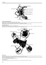
f) Subtank
The subtank installed under each ink tank complements the work of the ink tank, agitating the ink in the tank.
If the ink tank runs out of the ink while printing, the ink stored in the subtank is available, allowing the ink tank to be replaced without having to stop printing.
g) Ink supply valve
The ink supply valve is located between the ink tank and ink tube to prevent ink leakage from occurring when the ink tube on the ink tank side is opened during
replacement of the ink tank.
The ink supply valve is opened and closed by the valve open/close mechanism which is driven by the valve motor.
The ink tank unit (Left/Right) consist of tank bases each of which contains ink tanks for three colors and the ink tubes for three colors.
Ink supply valves for all colors are opened and closed at the same time.
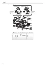
h) Subtank air passage valve
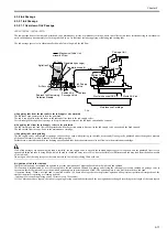
The subtank air passage valves keep the internal pressure of the subtank adequatly.
The subtank air passage valve is opened and closed by the valve open/close mechanism which is driven by the valve motor.
F-2-11
Ink Supply Valve Open/Closed Lever
Ink Supply
Valve Cam
Subtank
Air Passage Valve
Ink Supply Valve
Ink Supply Valve Open/Closed
Detection Sensor
Air Passage Valve Open/Closed Detection Sensor
Subtank Air Passage Valve Cam
Valve Motor
Subtank Air Passage Valve Open/Closed Lever
Subtank
Summary of Contents for iPF750 series
Page 1: ...Jul 25 2012 Service Manual iPF760 750 series ...
Page 2: ......
Page 6: ......
Page 11: ...Chapter 1 PRODUCT DESCRIPTION ...
Page 12: ......
Page 14: ...Contents 1 7 3 5 Self diagnostic Feature 1 71 1 7 3 6 Disposing of the Lithium Battery 1 72 ...
Page 87: ...Chapter 2 TECHNICAL REFERENCE ...
Page 88: ......
Page 99: ...Chapter 2 2 9 ...
Page 145: ...Chapter 3 INSTALLATION ...
Page 146: ......
Page 148: ......
Page 152: ......
Page 153: ...Chapter 4 DISASSEMBLY REASSEMBLY ...
Page 154: ......
Page 156: ......
Page 214: ...Chapter 4 4 58 2 Shaft Cleaner 1 F 4 119 1 ...
Page 215: ...Chapter 4 4 59 3 Upper Cover Hinge Catch 1 Roll Cover Slide Guide 2 F 4 120 2 1 ...
Page 218: ......
Page 219: ...Chapter 5 MAINTENANCE ...
Page 220: ......
Page 222: ......
Page 227: ...Chapter 5 5 5 ...
Page 228: ......
Page 229: ...Chapter 6 TROUBLESHOOTING ...
Page 230: ......
Page 232: ......
Page 250: ......
Page 251: ...Chapter 7 SERVICE MODE ...
Page 252: ......
Page 254: ......
Page 305: ......
Page 306: ......
Page 307: ...Chapter 8 ERROR CODE ...
Page 308: ......
Page 310: ......
Page 327: ...Jul 25 2012 ...
Page 328: ......


