5
5
5-13
5-13
Installation(Inner Finisher-A1) > Installation Procedure > Installation Procedure
Installation(Inner Finisher-A1) > Installation Procedure > Installation Procedure
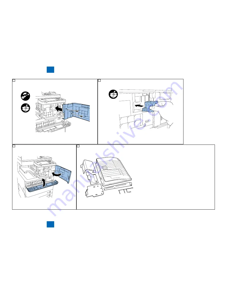
30) Fix the combined right front cover and inner cover contained in the finisher
carton box with 2 screws (RS-tight screw, M3x6).
x2
F-5-34
F-5-34
31) Set the supplied staple cartridge into the stapler.
F-5-35
F-5-35
32) Close all the external covers.
Stick the supplied main power label on the upper part of the
main power switch.
F-5-36
F-5-36
33) The following parts remain after installing the finisher. Make sure not to leave the remained parts at the site.
Delivery tray
1 pc.
2nd delivery tray
1 pc.(*1)
Stopper
1 pc.(*1)
Reversal guide
1 pc.
Right front cover
1 pc.
Inner cover (small)
1 pc.
Control panel lower cover
1 pc.
Sensor flag
1 pc.(*2)
Cap
2 pcs.
Protection cover
1 pc.
*1 only when the 2nd delivery tray is installed in the host machine
*2 2 pcs. only when the 2nd delivery tray is installed in the host machine
F-5-37
F-5-37
Summary of Contents for Inner Finisher Additional Tray-A1
Page 1: ...6 5 4 3 2 1 Inner Finisher A1 Inner Finisher Additional Tray A1 Service Manual ...
Page 4: ...0 0 ...
Page 7: ...Safety Precautions Notes Before it Works Serving ...
Page 9: ...1 1 Produt Outline Produt Outline Names of Parts Specifications Names of Parts ...
Page 14: ...2 2 Technology Technology Basic Configuration Work of Service ...
Page 19: ...3 3 Periodic Servicing Periodic Servicing Periodic Service Works ...
Page 81: ...Appendix Service Tools General Circuit Diagram ...


