


Chapter 7
7-30
1) Slide the cover [2].
- 1 screw [1]
2) Detach the cover while pulling the separation claw holder [4] toward the
front.
- 2 screws [3]
F-7-95
Be careful not to break the separation claw.
7.10.19 Potential Sensor Unit
7.10.19.1 Outline
0015-4943
iR5065 / iR 5055 / iR5075 / / /
The potential sensor unit includes the following 4 parts:
- Potential control PCB
- Potential sensor
- Potential sensor relay harness (between the relay connector and the
potential control PCB)
- Potential sensor harness (between the potential sensor and the relay
connector)
Be sure to replace them at the same time.
7.10.19.2 Before Removing Potential Sensor Unit
0015-6700
iR5065 / iR 5055 / iR5075 / / /
1) Detach the front cover.
Reference[Removing the Front
Cover]
2) Detach the toner supply cover.
Reference[Removing the
Toner Supply Cover]
3) Remove the primary fan duct.
Reference[Removing
Primary fan Duct]
7.10.19.3 Removing Potential Sensor Unit
0015-4952
iR5065 / iR 5055 / iR5075 / / /
1) Remove the potential sensor unit [3].
- 1 connector [1]
- 1 screw [2]
- Cable (free from the cable guide)
F-7-96
7.10.20 Charging Wire
7.10.20.1 Outline
0015-9965
iR5065 / iR 5055 / iR5075 / / /
The photosensitive drum is surrounded by 3 charging wires; the primary
charging wire, the pre-transfer charging wire, and the transfer/separation
charging wire.
These charging wires are newly adopted brown wires (0.06 mm in diameter).
Do not use a gold-plated wire that has been used in the past; otherwise, image
fault may occur.
Further, be sure to use a strengthened polishing pad (in a blue holder) as the
cleaning pad for the primary charging assembly and the transfer charging as-
sembly.
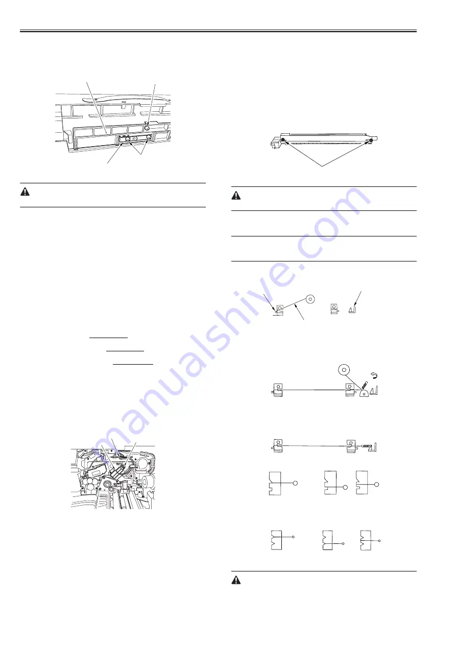
7.10.20.2 Routing Charging Wire
0015-9967
iR5065 / iR 5055 / iR5075 / / /
All charging wires (except the grid wire) are routed more or less in the same
way; the following cites the primary charging assembly.
1) Remove the shield plates (left, right) of the charging assembly. To prevent
deformation (deflection) in the primary charging assembly, be sure to
work separately for the left shielding plate and the right shielding plate
(do not loosen the screws [1] of both shielding plates at the same time.)
2) Remove the wire cleaner.
F-7-97
For other charging assemblies, remove the 2 covers.
3) Free a length of about 5 cm of the charging wire (0.06 mm in diameter)
from the charging wire reel, and form a loop at its end with a diameter of
about 2 mm.
MEMO:
To form a loop, wind the charging wire around a hex key once, and turn the
hex key 3 to 4 times; then, twist the charging wire.
4) Cut the end (excess) of the twisted wire.
5) Hook the loop on the stud.
F-7-98
6) At the rear, hook the charging wire on the charging wire positioning plate;
then, hook the charging wire tension spring on the charging wire where
indicated to the following figure.
F-7-99
7) Cut off the excess of the charging wire with nippers.
8) Pick the end of the charging wire tension spring with tweezers, and hook
it on the charging power supply electrode. In the case of the pre-transfer
charging assembly, hook the spring on the pin at the front.
F-7-100
F-7-101
Make sure the followings:
- The charging wire must not be bent or twisted.
[2]
[1]
[4]
[3]
[1]
[2]
[3]
[1]
Charging electrode
(Rear)
(Front) Charging wire
Reel
Stud
(Correct)
(Wrong)
Grid side
(Correct)
(Wrong)
Summary of Contents for imageRUNNER 5065 series
Page 1: ...Feb 26 2007 Service Manual iR5075 5065 5055 Series ...
Page 2: ......
Page 6: ......
Page 27: ...Chapter 1 Introduction ...
Page 28: ......
Page 30: ......
Page 52: ......
Page 53: ...Chapter 2 Installation ...
Page 54: ......
Page 98: ...Chapter 2 2 42 ...
Page 99: ...Chapter 3 Basic Operation ...
Page 100: ......
Page 102: ......
Page 108: ......
Page 109: ...Chapter 4 Main Controller ...
Page 110: ......
Page 112: ......
Page 129: ...Chapter 5 Original Exposure System ...
Page 130: ......
Page 162: ......
Page 163: ...Chapter 6 Laser Exposure ...
Page 164: ......
Page 166: ......
Page 172: ......
Page 173: ...Chapter 7 Image Formation ...
Page 174: ......
Page 178: ......
Page 210: ......
Page 211: ...Chapter 8 Pickup Feeding System ...
Page 212: ......
Page 263: ...Chapter 9 Fixing System ...
Page 264: ......
Page 268: ......
Page 307: ...Chapter 10 External and Controls ...
Page 308: ......
Page 312: ......
Page 321: ...Chapter 10 10 9 F 10 8 ...
Page 345: ...Chapter 11 MEAP ...
Page 346: ......
Page 348: ......
Page 389: ...Chapter 12 RDS ...
Page 390: ......
Page 392: ......
Page 399: ...Chapter 13 Maintenance and Inspection ...
Page 400: ......
Page 402: ......
Page 411: ...Chapter 14 Standards and Adjustments ...
Page 412: ......
Page 440: ......
Page 441: ...Chapter 15 Correcting Faulty Images ...
Page 442: ......
Page 444: ......
Page 470: ......
Page 471: ...Chapter 16 Self Diagnosis ...
Page 472: ......
Page 474: ......
Page 493: ...Chapter 17 Service Mode ...
Page 494: ......
Page 496: ......
Page 552: ......
Page 553: ...Chapter 18 Upgrading ...
Page 554: ......
Page 556: ......
Page 572: ...Chapter 18 18 16 F 18 29 2 Click Start F 18 30 3 When the session has ended click OK ...
Page 587: ...Chapter 18 18 31 F 18 59 2 Select the data to download F 18 60 3 Click Start ...
Page 589: ...Chapter 19 Service Tools ...
Page 590: ......
Page 592: ......
Page 595: ...Feb 26 2007 ...
Page 596: ......


