


Chapter 2
2-8
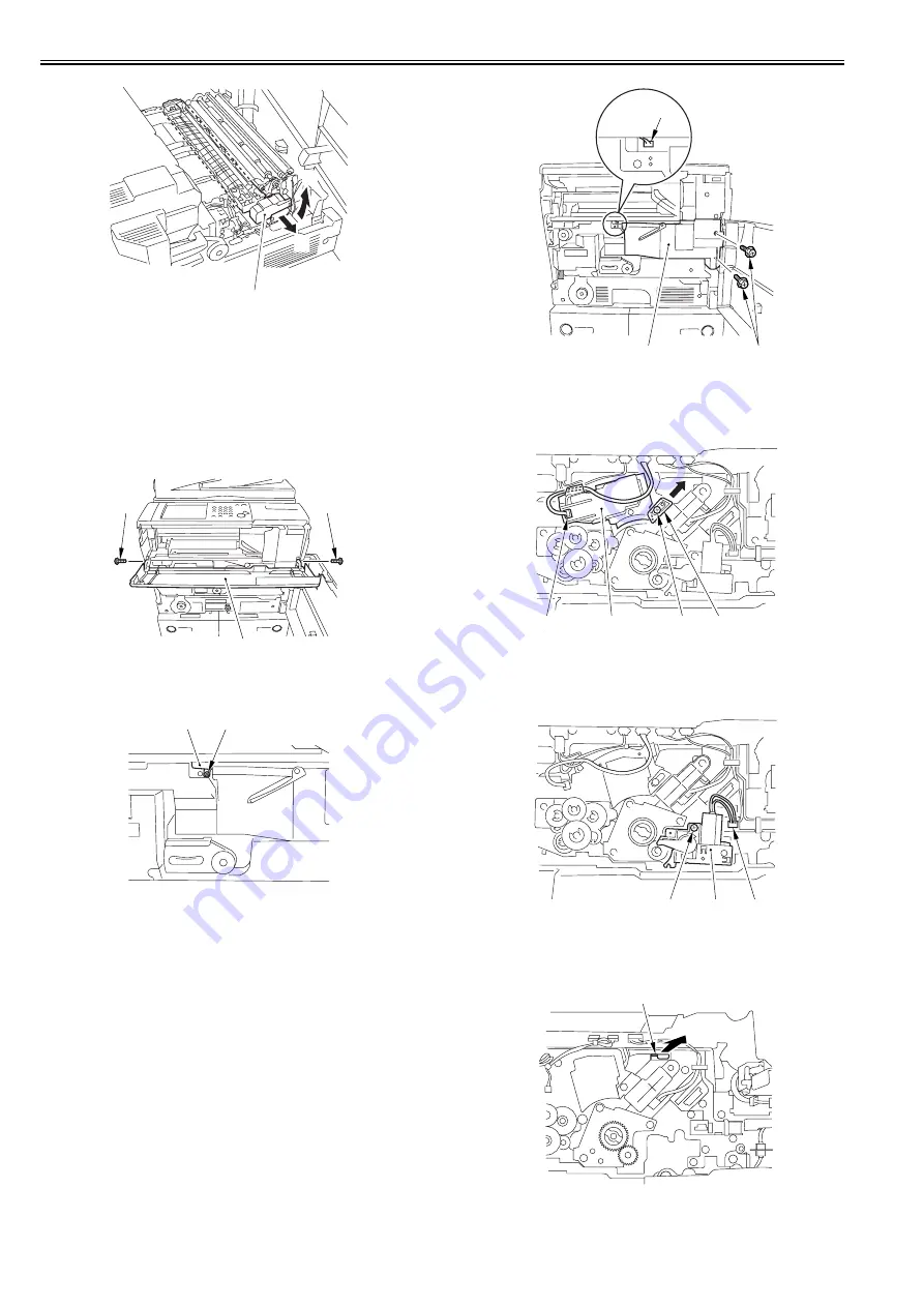
F-2-21
4) Check the transfer/separation charging assembly. If any dirt or paper
powder is attached onto the assembly, clean it with alcohol solutions.
5) Mount the transfer/separation assembly using the steps to remove it but in
reverse.
6) Attach the feeder assembly front cover (right) with the 2 screws (use the
screws removed in the step 1). Put back the fixing/feeder assembly and
the duplexing unit to the original positions (leave the fixing/feeder
assembly release lever as it is).
7) Open the toner replacement cover.
8) Detach the toner replacement cover [1].
- 2 screws [2]
F-2-22
9) Detach the connector cover [1].
- 1 screw [2]
F-2-23
10) Remove the 2 screws [1] and disconnect the connector [2]; then, remove
the primary fan duct [3].
F-2-24
11) Loosen the screw [1] and shift the charging assembly mount [2] in the
direction of the arrow; then, tighten the screw once again.
12) Disconnect the connector [3], and remove the primary charging
assembly [4].
F-2-25
13) Check the primary charging assembly. If any dirt or paper powder is
attached onto the assembly, clean it with alcohol solutions.
14) Disconnect the connector [1] and remove the screw [2]; then, slide the
pre-transfer charging assembly [3] out.
F-2-26
15) Check the pre-transfer charging assembly. If any dirt or paper powder is
attached onto the assembly, clean it with alcohol solutions.
16) Remove the dustproof glass [1].
F-2-27
17) Check and clean the dustproof glass with a blower brush.
[1]
[A]
[B]
[2]
[2]
[1]
[2]
[1]
[1]
[2]
[3]
[3]
[4]
[2]
[1]
[1]
[2]
[3]
[1]
Summary of Contents for imageRUNNER 5065 series
Page 1: ...Feb 26 2007 Service Manual iR5075 5065 5055 Series ...
Page 2: ......
Page 6: ......
Page 27: ...Chapter 1 Introduction ...
Page 28: ......
Page 30: ......
Page 52: ......
Page 53: ...Chapter 2 Installation ...
Page 54: ......
Page 98: ...Chapter 2 2 42 ...
Page 99: ...Chapter 3 Basic Operation ...
Page 100: ......
Page 102: ......
Page 108: ......
Page 109: ...Chapter 4 Main Controller ...
Page 110: ......
Page 112: ......
Page 129: ...Chapter 5 Original Exposure System ...
Page 130: ......
Page 162: ......
Page 163: ...Chapter 6 Laser Exposure ...
Page 164: ......
Page 166: ......
Page 172: ......
Page 173: ...Chapter 7 Image Formation ...
Page 174: ......
Page 178: ......
Page 210: ......
Page 211: ...Chapter 8 Pickup Feeding System ...
Page 212: ......
Page 263: ...Chapter 9 Fixing System ...
Page 264: ......
Page 268: ......
Page 307: ...Chapter 10 External and Controls ...
Page 308: ......
Page 312: ......
Page 321: ...Chapter 10 10 9 F 10 8 ...
Page 345: ...Chapter 11 MEAP ...
Page 346: ......
Page 348: ......
Page 389: ...Chapter 12 RDS ...
Page 390: ......
Page 392: ......
Page 399: ...Chapter 13 Maintenance and Inspection ...
Page 400: ......
Page 402: ......
Page 411: ...Chapter 14 Standards and Adjustments ...
Page 412: ......
Page 440: ......
Page 441: ...Chapter 15 Correcting Faulty Images ...
Page 442: ......
Page 444: ......
Page 470: ......
Page 471: ...Chapter 16 Self Diagnosis ...
Page 472: ......
Page 474: ......
Page 493: ...Chapter 17 Service Mode ...
Page 494: ......
Page 496: ......
Page 552: ......
Page 553: ...Chapter 18 Upgrading ...
Page 554: ......
Page 556: ......
Page 572: ...Chapter 18 18 16 F 18 29 2 Click Start F 18 30 3 When the session has ended click OK ...
Page 587: ...Chapter 18 18 31 F 18 59 2 Select the data to download F 18 60 3 Click Start ...
Page 589: ...Chapter 19 Service Tools ...
Page 590: ......
Page 592: ......
Page 595: ...Feb 26 2007 ...
Page 596: ......


