


Chapter 17
17-2
1) Press the asterisk key (
) on the operation panel.
2) Press 2 and 8 simultaneously on the numeric keypad.
3) Press the asterisk key (
)on the operation panel.
The initial screen (see below) now appears.
F-17-3
17.1.3 Exiting service modes
0015-5499
iR5065 / iR 5055 / iR5075 / / /
When the reset key is pressed once, the display returns to the service mode initial screen.
When the reset key is pressed twice, the service modes are exited, and the display returns to the user screen (standard screen).
When using the ADJUST, FUNCTION or OPTION service mode, be sure to turn the main power switch ON/OFF after exiting the mode.
17.1.4 Backing Up Service Mode
0015-5501
iR5065 / iR 5055 / iR5075 / / /
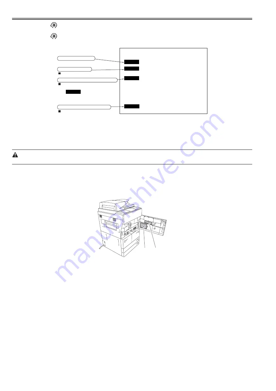
All machines are inspected at time of shipment, and adjustment values are recorded on their service labels. If you have replaced the reader controller PCB or the
DC controller PCB, or if you have initialized the RAM, ADJUST and OPTION will be reset to their default settings. If you have made adjustments and changed
any of the settings, be sure to update the settings recorded on the service label. If specific items are missing on the label, use its blank space.
F-17-4
[1] Service label (for main controller PCB/DC controller PCB)
[2] Service label (for reader controller PCB)
17.1.5 Initial screen
0015-5502
iR5065 / iR 5055 / iR5075 / / /
COPIER
FEEDER
SORTER
SORTER
ADF service modes
Displayed only when the ADF is attached.
Displayed only when the finisher is attached.
BOARD
Option board service modes
Displayed only when an option board is
attached.
Copier service modes
Sorter/finisher service modes
(There are no modes for the sorter,
so isn’t displayed even
when the sorter is attached.)
[1]
[2]
Summary of Contents for imageRUNNER 5065 series
Page 1: ...Feb 26 2007 Service Manual iR5075 5065 5055 Series ...
Page 2: ......
Page 6: ......
Page 27: ...Chapter 1 Introduction ...
Page 28: ......
Page 30: ......
Page 52: ......
Page 53: ...Chapter 2 Installation ...
Page 54: ......
Page 98: ...Chapter 2 2 42 ...
Page 99: ...Chapter 3 Basic Operation ...
Page 100: ......
Page 102: ......
Page 108: ......
Page 109: ...Chapter 4 Main Controller ...
Page 110: ......
Page 112: ......
Page 129: ...Chapter 5 Original Exposure System ...
Page 130: ......
Page 162: ......
Page 163: ...Chapter 6 Laser Exposure ...
Page 164: ......
Page 166: ......
Page 172: ......
Page 173: ...Chapter 7 Image Formation ...
Page 174: ......
Page 178: ......
Page 210: ......
Page 211: ...Chapter 8 Pickup Feeding System ...
Page 212: ......
Page 263: ...Chapter 9 Fixing System ...
Page 264: ......
Page 268: ......
Page 307: ...Chapter 10 External and Controls ...
Page 308: ......
Page 312: ......
Page 321: ...Chapter 10 10 9 F 10 8 ...
Page 345: ...Chapter 11 MEAP ...
Page 346: ......
Page 348: ......
Page 389: ...Chapter 12 RDS ...
Page 390: ......
Page 392: ......
Page 399: ...Chapter 13 Maintenance and Inspection ...
Page 400: ......
Page 402: ......
Page 411: ...Chapter 14 Standards and Adjustments ...
Page 412: ......
Page 440: ......
Page 441: ...Chapter 15 Correcting Faulty Images ...
Page 442: ......
Page 444: ......
Page 470: ......
Page 471: ...Chapter 16 Self Diagnosis ...
Page 472: ......
Page 474: ......
Page 493: ...Chapter 17 Service Mode ...
Page 494: ......
Page 496: ......
Page 552: ......
Page 553: ...Chapter 18 Upgrading ...
Page 554: ......
Page 556: ......
Page 572: ...Chapter 18 18 16 F 18 29 2 Click Start F 18 30 3 When the session has ended click OK ...
Page 587: ...Chapter 18 18 31 F 18 59 2 Select the data to download F 18 60 3 Click Start ...
Page 589: ...Chapter 19 Service Tools ...
Page 590: ......
Page 592: ......
Page 595: ...Feb 26 2007 ...
Page 596: ......


