


Chapter 10
10-7
10.4.3 Protection Function
10.4.3.1 Protective Functions
0015-4637
iR5065 / iR 5055 / iR5075 / / /
The machine's DC power supply PCB and the power supply PCB for its accessories are equipped with overcurrent and overvoltage protective functions that will
cut off power to prevent damage to circuitry in the event of an overcurrent or overvoltage occurring as a result of a short circuit or other fault.
A fault in 3VB (uninterruptive power supply) will cut off all power of the machine; on the other hand, a fault in any other power supply will cut off all power to
loads other than 3VB (uninterruptive power supply).
If a fault has occurred in 3VB (uninterruptive power supply), turn off the main power switch of the printer unit, and remove the cause that has activated the protective
circuit; then, replace the DC power supply PCB. (The fuse on the DC power supply PCB is likely to have blown.)
Other than that, turn off the main power switch of the printer unit, and remove the cause that has activated the protective circuit; then, leave the machine alone for
about 3 min or more, and turn the power back on to reset the protective circuit.
10.4.4 Backup Battery
10.4.4.1 Backup Battery
0015-4638
iR5065 / iR 5055 / iR5075 / / /
The machine's main controller PCB and DC controller PCB are equipped with each of one lithium battery that serves as a source of backup power to retain various
data in the event of a power outage or disconnection of the power plug.
T-10-17
You must always be sure that the battery is replaced correctly. Be sure to replace it with a battery of a type indicated by the manufacturer of the unit (bearing the
same model name or equivalent).
Be sure also to dispose of the removed battery as instructed by the manufacturer of the battery.
10.4.5 Energy-Saving Function
10.4.5.1 Overview
0015-4639
iR5065 / iR 5055 / iR5075 / / /
1. Standby State
When the machine is in a standby state, all its loads are supplied with power and the machine is ready to start operation at any time.
2. Sleep State
2-1. Sleep 1
When the machine is in sleep 1, its laser scanner will not rotate even when a key on the control panel is pressed.
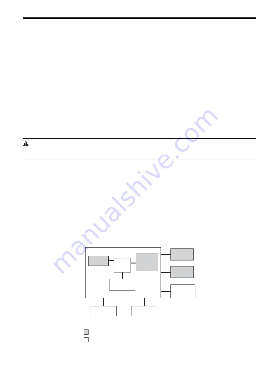
2-2. Sleep 3
When the machine is in sleep 3, only 3VB on the DC power supply PCB is supplied with power.
The machine moves from sleep 3 to standby in response to the following:
- print job
- press on the control panel power switch
- fax reception
- fax delayed transmission
The following shows the loads that remain supplied with power when the machine is in sleep 3.
F-10-6
3. AC Off State
Battery specifications
manganese dioxide lithium battery
(3 V, 1000 mAh)
Battery life
main controller PCB: about 8.8 yr
(with power plug disconnected)
Battery replacement
not possible in the field on its own
CPU
SDRAM
LAN
controller
block
Image
processing
block
Control panel
power switch
Fax
reception
detection
Hard disk
drive
Scanner unit
Printer unit
supplied with power in sleep 3
not supplied with power in sleep 3
Main controller PCB
Summary of Contents for imageRUNNER 5065 series
Page 1: ...Feb 26 2007 Service Manual iR5075 5065 5055 Series ...
Page 2: ......
Page 6: ......
Page 27: ...Chapter 1 Introduction ...
Page 28: ......
Page 30: ......
Page 52: ......
Page 53: ...Chapter 2 Installation ...
Page 54: ......
Page 98: ...Chapter 2 2 42 ...
Page 99: ...Chapter 3 Basic Operation ...
Page 100: ......
Page 102: ......
Page 108: ......
Page 109: ...Chapter 4 Main Controller ...
Page 110: ......
Page 112: ......
Page 129: ...Chapter 5 Original Exposure System ...
Page 130: ......
Page 162: ......
Page 163: ...Chapter 6 Laser Exposure ...
Page 164: ......
Page 166: ......
Page 172: ......
Page 173: ...Chapter 7 Image Formation ...
Page 174: ......
Page 178: ......
Page 210: ......
Page 211: ...Chapter 8 Pickup Feeding System ...
Page 212: ......
Page 263: ...Chapter 9 Fixing System ...
Page 264: ......
Page 268: ......
Page 307: ...Chapter 10 External and Controls ...
Page 308: ......
Page 312: ......
Page 321: ...Chapter 10 10 9 F 10 8 ...
Page 345: ...Chapter 11 MEAP ...
Page 346: ......
Page 348: ......
Page 389: ...Chapter 12 RDS ...
Page 390: ......
Page 392: ......
Page 399: ...Chapter 13 Maintenance and Inspection ...
Page 400: ......
Page 402: ......
Page 411: ...Chapter 14 Standards and Adjustments ...
Page 412: ......
Page 440: ......
Page 441: ...Chapter 15 Correcting Faulty Images ...
Page 442: ......
Page 444: ......
Page 470: ......
Page 471: ...Chapter 16 Self Diagnosis ...
Page 472: ......
Page 474: ......
Page 493: ...Chapter 17 Service Mode ...
Page 494: ......
Page 496: ......
Page 552: ......
Page 553: ...Chapter 18 Upgrading ...
Page 554: ......
Page 556: ......
Page 572: ...Chapter 18 18 16 F 18 29 2 Click Start F 18 30 3 When the session has ended click OK ...
Page 587: ...Chapter 18 18 31 F 18 59 2 Select the data to download F 18 60 3 Click Start ...
Page 589: ...Chapter 19 Service Tools ...
Page 590: ......
Page 592: ......
Page 595: ...Feb 26 2007 ...
Page 596: ......


