


Chapter 14
14-4
F-14-4
F-14-5
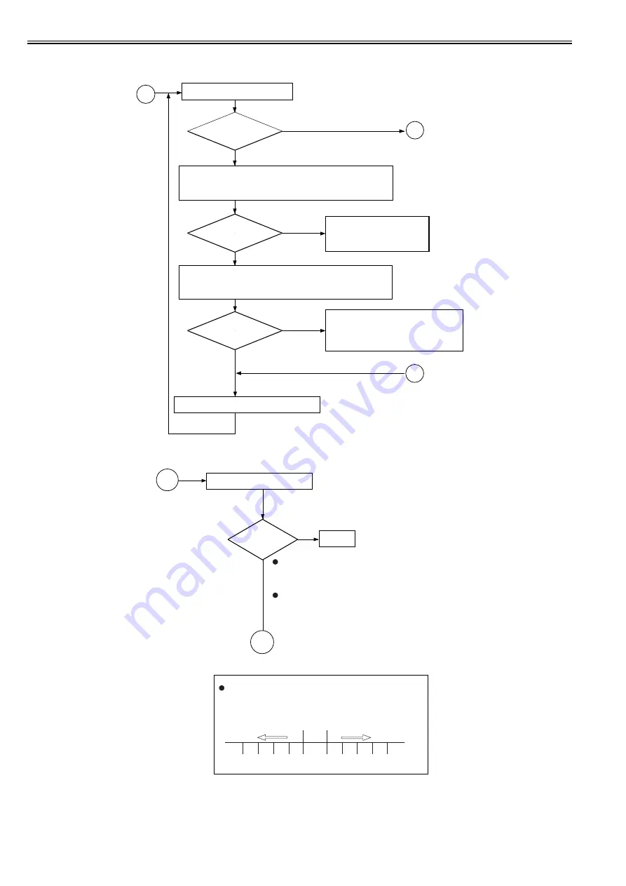
14.1.4 Making Checks on the Reader Unit
0015-5283
iR5065 / iR 5055 / iR5075 / / /
B
Is the density
too low or too high (too
light or too dark)?
Are the
readings ± 6 V of the
target value?
(*1)
Adjust the offset of the VD target potential.
<
Checking the Solid Black Density
>
YES
NO
NO
YES
NO
YES
Generate a solid black print.
Check the following readings (VL1 target value) in service mode:
COPIER>DISPLAY>DPOT>VL1M (for copier image)
COPIER>DISPLAY>DPOT>VL1M-P (for printer image)
Check the following readings (VD target value) in service mode:
COPIER>DISPLAY>DPOT>VDM (for copier image)
COPIER>DISPLAY>DPOT>VDM-P (for printer image)
Check the following, and replace them if
necessary:
1. Laser (for output)
2. Potential control system
3. Photosensitive drum
Check the primary charging
system; if normal, replace the
photosensitive drum.
Are the
readings ± 6 V of the
target value?
(*2)
C
D
<Checking the Halftone Density>
Generate a halftone image.
End.
To check a copier image,
See if No. 6 and No. 7 (halftone) of the Test Chart is
reproduced to the more or less the same density.
To check a printer (PDL) image,
See if the density of the halftone area represents the
original data properly.
Is the halftone
density optimum?
NO
YES
Adjusting the Offset Value of the VD Target Potential
(VD-OFFSET/VD-OFFSET-P)
COPIER>ADJUST>V-CONT>VD-OFST (for copier image)
COPIER>ADJUST>V-CONT>VD-VD-OFST-P (for printer image)
Default
Lighter image
Darker image
-5 -4 -3 -2 -1 0 +1 +2 +3 +4 +5
C
D
Summary of Contents for imageRUNNER 5065 series
Page 1: ...Feb 26 2007 Service Manual iR5075 5065 5055 Series ...
Page 2: ......
Page 6: ......
Page 27: ...Chapter 1 Introduction ...
Page 28: ......
Page 30: ......
Page 52: ......
Page 53: ...Chapter 2 Installation ...
Page 54: ......
Page 98: ...Chapter 2 2 42 ...
Page 99: ...Chapter 3 Basic Operation ...
Page 100: ......
Page 102: ......
Page 108: ......
Page 109: ...Chapter 4 Main Controller ...
Page 110: ......
Page 112: ......
Page 129: ...Chapter 5 Original Exposure System ...
Page 130: ......
Page 162: ......
Page 163: ...Chapter 6 Laser Exposure ...
Page 164: ......
Page 166: ......
Page 172: ......
Page 173: ...Chapter 7 Image Formation ...
Page 174: ......
Page 178: ......
Page 210: ......
Page 211: ...Chapter 8 Pickup Feeding System ...
Page 212: ......
Page 263: ...Chapter 9 Fixing System ...
Page 264: ......
Page 268: ......
Page 307: ...Chapter 10 External and Controls ...
Page 308: ......
Page 312: ......
Page 321: ...Chapter 10 10 9 F 10 8 ...
Page 345: ...Chapter 11 MEAP ...
Page 346: ......
Page 348: ......
Page 389: ...Chapter 12 RDS ...
Page 390: ......
Page 392: ......
Page 399: ...Chapter 13 Maintenance and Inspection ...
Page 400: ......
Page 402: ......
Page 411: ...Chapter 14 Standards and Adjustments ...
Page 412: ......
Page 440: ......
Page 441: ...Chapter 15 Correcting Faulty Images ...
Page 442: ......
Page 444: ......
Page 470: ......
Page 471: ...Chapter 16 Self Diagnosis ...
Page 472: ......
Page 474: ......
Page 493: ...Chapter 17 Service Mode ...
Page 494: ......
Page 496: ......
Page 552: ......
Page 553: ...Chapter 18 Upgrading ...
Page 554: ......
Page 556: ......
Page 572: ...Chapter 18 18 16 F 18 29 2 Click Start F 18 30 3 When the session has ended click OK ...
Page 587: ...Chapter 18 18 31 F 18 59 2 Select the data to download F 18 60 3 Click Start ...
Page 589: ...Chapter 19 Service Tools ...
Page 590: ......
Page 592: ......
Page 595: ...Feb 26 2007 ...
Page 596: ......


