


Chapter 2
2-22
1) Check to see that 'ID00000001 to ID00001000' has been created in
> [System Settings] > [Dep ID Mangement] > [Registor Dept.ID/Password] > [Page
Totals]. (In the case that '1' has been input as the first number by the service mode; COPIER > FUNCTION > INSTALL > CARD)
2) Press the reset key to escape the user mode screen.
3) Select
> [System Settings] > [Network Settings] > [TCP/IP Settings] > [IP Address Settings], and then make the setting of [IP Address], [Gateway Address],
[Subnet Mask] according to the user environment
4) Press the reset key to escape the user mode screen.
5) Operate the touch panel following the instruction on the screen of shutdown sequence in order to turn off the main power switch.
6) Turn on the main power switch.
7)
> [System Settings] > [System Maneger Settings], and then input any number into [System Maneger ID] and [System Password].
8) Press the reset key to escape the user mode screen.
9) Turn off the power according to the shutdown sequence.
2.6 Installing the Original Holder
2.6.1 Checking Contents
0015-4777
iR5065 / iR 5055 / iR5075 / / /
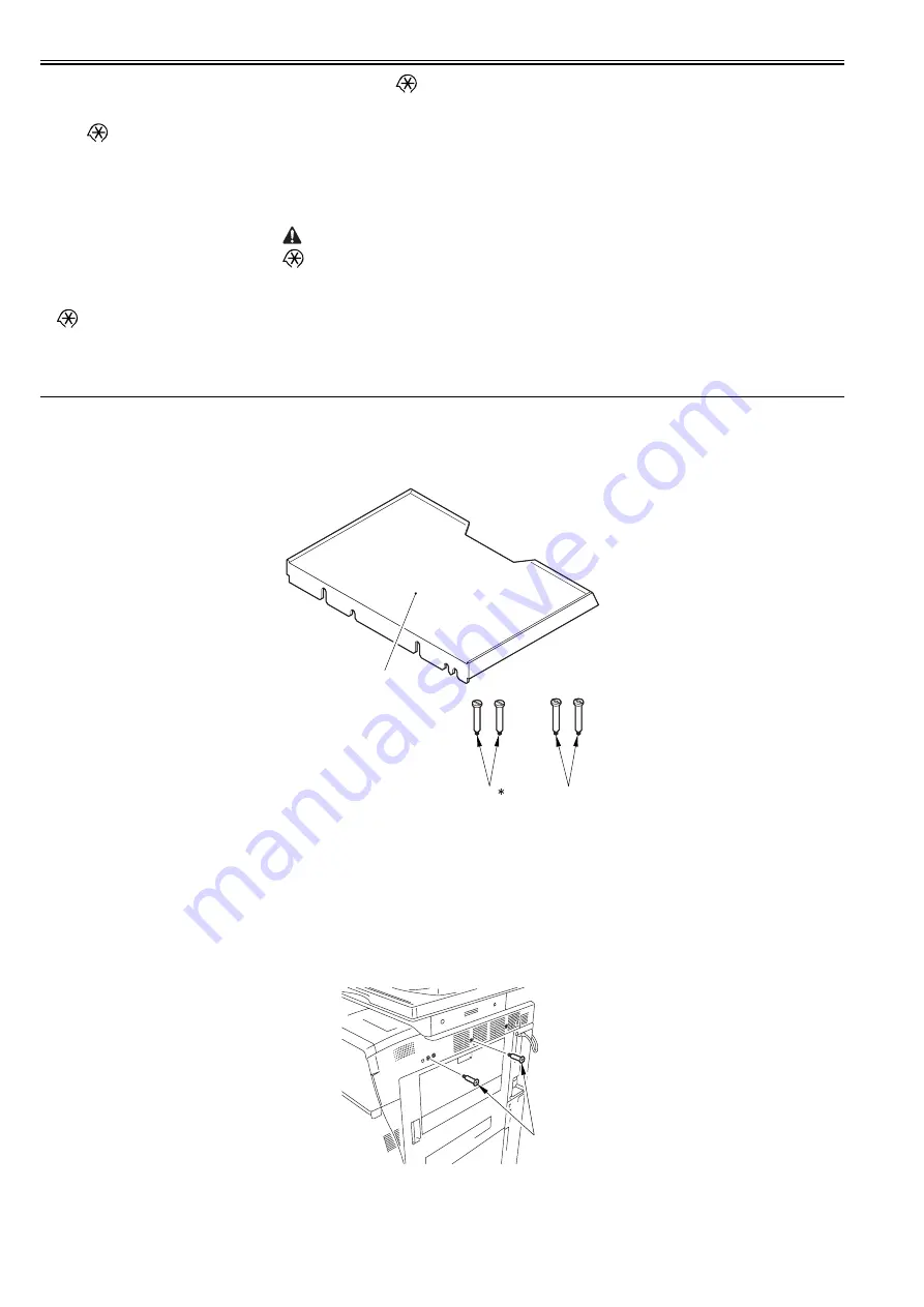
Document Tray-K1
F-2-82
2.6.2 Installation Procedure
0015-4778
iR5065 / iR 5055 / iR5075 / / /
1) Tighten the 2 stepped screws (M4X33) [1] to the upper cover (right).
F-2-83
2) Hook the document tray [1] to the stepped screws tightened in the step 1.
> [System Settings] > [System Maneger Settings] is selected and
[System Maneger ID] and [System Password] are registered, 'Registration
of card to the device' is impossible to execute in the setting of iWAM.
[1]
Document Tray
1 pc.
[2]*
Stepped Screw (M4X31)
2 pc.
[3]
Stepped Screw (M4X33)
2 pc.
* Not used with this host machine.
[1]
[2]
[3]
[1]
Summary of Contents for imageRUNNER 5055 series
Page 1: ...Feb 26 2007 Service Manual iR5075 5065 5055 Series ...
Page 2: ......
Page 6: ......
Page 27: ...Chapter 1 Introduction ...
Page 28: ......
Page 30: ......
Page 52: ......
Page 53: ...Chapter 2 Installation ...
Page 54: ......
Page 98: ...Chapter 2 2 42 ...
Page 99: ...Chapter 3 Basic Operation ...
Page 100: ......
Page 102: ......
Page 108: ......
Page 109: ...Chapter 4 Main Controller ...
Page 110: ......
Page 112: ......
Page 129: ...Chapter 5 Original Exposure System ...
Page 130: ......
Page 162: ......
Page 163: ...Chapter 6 Laser Exposure ...
Page 164: ......
Page 166: ......
Page 172: ......
Page 173: ...Chapter 7 Image Formation ...
Page 174: ......
Page 178: ......
Page 210: ......
Page 211: ...Chapter 8 Pickup Feeding System ...
Page 212: ......
Page 263: ...Chapter 9 Fixing System ...
Page 264: ......
Page 268: ......
Page 307: ...Chapter 10 External and Controls ...
Page 308: ......
Page 312: ......
Page 321: ...Chapter 10 10 9 F 10 8 ...
Page 345: ...Chapter 11 MEAP ...
Page 346: ......
Page 348: ......
Page 389: ...Chapter 12 RDS ...
Page 390: ......
Page 392: ......
Page 399: ...Chapter 13 Maintenance and Inspection ...
Page 400: ......
Page 402: ......
Page 411: ...Chapter 14 Standards and Adjustments ...
Page 412: ......
Page 440: ......
Page 441: ...Chapter 15 Correcting Faulty Images ...
Page 442: ......
Page 444: ......
Page 470: ......
Page 471: ...Chapter 16 Self Diagnosis ...
Page 472: ......
Page 474: ......
Page 493: ...Chapter 17 Service Mode ...
Page 494: ......
Page 496: ......
Page 552: ......
Page 553: ...Chapter 18 Upgrading ...
Page 554: ......
Page 556: ......
Page 572: ...Chapter 18 18 16 F 18 29 2 Click Start F 18 30 3 When the session has ended click OK ...
Page 587: ...Chapter 18 18 31 F 18 59 2 Select the data to download F 18 60 3 Click Start ...
Page 589: ...Chapter 19 Service Tools ...
Page 590: ......
Page 592: ......
Page 595: ...Feb 26 2007 ...
Page 596: ......


