


Chapter 10
10-30
F-10-109
10.5.29 Fixing Heater Power Supply Cooling Fan
10.5.29.1 Before Removing the Fixing Heater Power
Supply Cooling Fan
0015-5163
iR5065 / iR 5055 / iR5075 / / /
1) Detach the left cover (upper).
Reference[Removing the
Left Cover (Upper)]
2) Detach the left cover (middle).
Reference[Removing the
Left Cover (Middle)]
10.5.29.2 Removing the Fixing Heater Power Supply
Cooling Fan
0015-5166
iR5065 / iR 5055 / iR5075 / / /
1) Detach the PCB cover [2].
- Screw [1] 5pc.
F-10-110
2) Open the 2 wire saddles [1].
3) Disconnect the 7 connectors [2].
4) Detach the fixing heater power supply unit [4].
- Screw [3] 3pc.
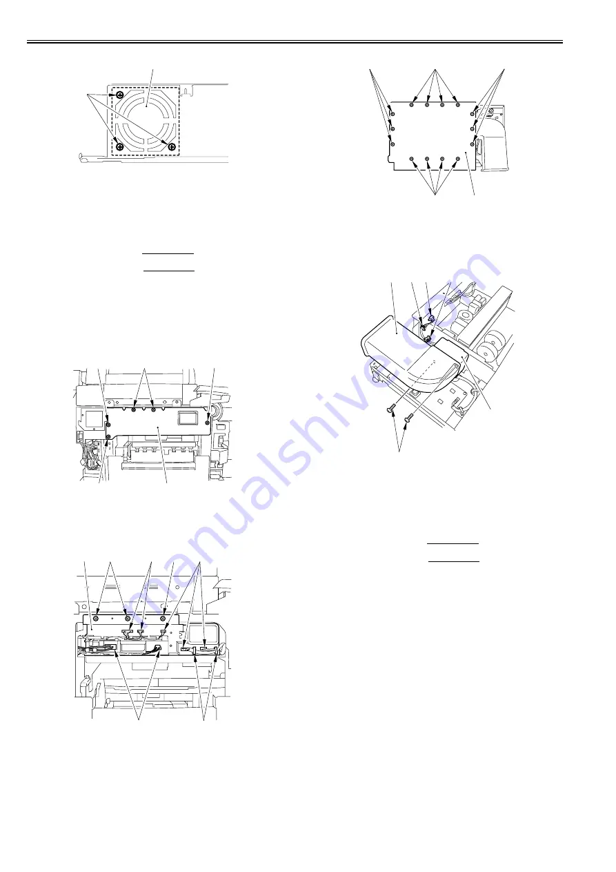
F-10-111
5) Detach the fixing heater power supply unit cover [2].
- Screw [1] 14pc.
F-10-112
6) Detach the duct [2].
- Screw [1] 2pc.
7) Detach the fixing heater power supply fan [5].
- Connector [3] 1pc.
- Wire saddle [4] 2pc.
F-10-113
10.5.30 Circulation Duct Fan
10.5.30.1 Before Removing the Circulation Duct Fan
0015-5167
iR5065 / iR 5055 / iR5075 / / /
1) Detach the left cover (upper).
Reference[Removing the
Left Cover (Upper)]
2) Detach the left cover (middle).
Reference[Removing the
Left Cover (Middle)]
10.5.30.2 Removing the Circulation Duct Fan
0015-5169
iR5065 / iR 5055 / iR5075 / / /
1) Free the harness [1] from the harness guide [2].
2) Disconnect the connector [3].
3) Detach the fixing heater power supply cooling fan [5] together with its
duct.
- Screw [4] 3pc.
[1]
[2]
[1]
[1]
[1]
[1]
[2]
[1]
[2]
[2]
[2]
[3]
[3]
[4]
[1]
[1]
[1]
[1]
[2]
[1]
[2]
[3]
[4]
[4]
[5]
Summary of Contents for imageRUNNER 5055 series
Page 1: ...Feb 26 2007 Service Manual iR5075 5065 5055 Series ...
Page 2: ......
Page 6: ......
Page 27: ...Chapter 1 Introduction ...
Page 28: ......
Page 30: ......
Page 52: ......
Page 53: ...Chapter 2 Installation ...
Page 54: ......
Page 98: ...Chapter 2 2 42 ...
Page 99: ...Chapter 3 Basic Operation ...
Page 100: ......
Page 102: ......
Page 108: ......
Page 109: ...Chapter 4 Main Controller ...
Page 110: ......
Page 112: ......
Page 129: ...Chapter 5 Original Exposure System ...
Page 130: ......
Page 162: ......
Page 163: ...Chapter 6 Laser Exposure ...
Page 164: ......
Page 166: ......
Page 172: ......
Page 173: ...Chapter 7 Image Formation ...
Page 174: ......
Page 178: ......
Page 210: ......
Page 211: ...Chapter 8 Pickup Feeding System ...
Page 212: ......
Page 263: ...Chapter 9 Fixing System ...
Page 264: ......
Page 268: ......
Page 307: ...Chapter 10 External and Controls ...
Page 308: ......
Page 312: ......
Page 321: ...Chapter 10 10 9 F 10 8 ...
Page 345: ...Chapter 11 MEAP ...
Page 346: ......
Page 348: ......
Page 389: ...Chapter 12 RDS ...
Page 390: ......
Page 392: ......
Page 399: ...Chapter 13 Maintenance and Inspection ...
Page 400: ......
Page 402: ......
Page 411: ...Chapter 14 Standards and Adjustments ...
Page 412: ......
Page 440: ......
Page 441: ...Chapter 15 Correcting Faulty Images ...
Page 442: ......
Page 444: ......
Page 470: ......
Page 471: ...Chapter 16 Self Diagnosis ...
Page 472: ......
Page 474: ......
Page 493: ...Chapter 17 Service Mode ...
Page 494: ......
Page 496: ......
Page 552: ......
Page 553: ...Chapter 18 Upgrading ...
Page 554: ......
Page 556: ......
Page 572: ...Chapter 18 18 16 F 18 29 2 Click Start F 18 30 3 When the session has ended click OK ...
Page 587: ...Chapter 18 18 31 F 18 59 2 Select the data to download F 18 60 3 Click Start ...
Page 589: ...Chapter 19 Service Tools ...
Page 590: ......
Page 592: ......
Page 595: ...Feb 26 2007 ...
Page 596: ......


