


Chapter 7
7-15
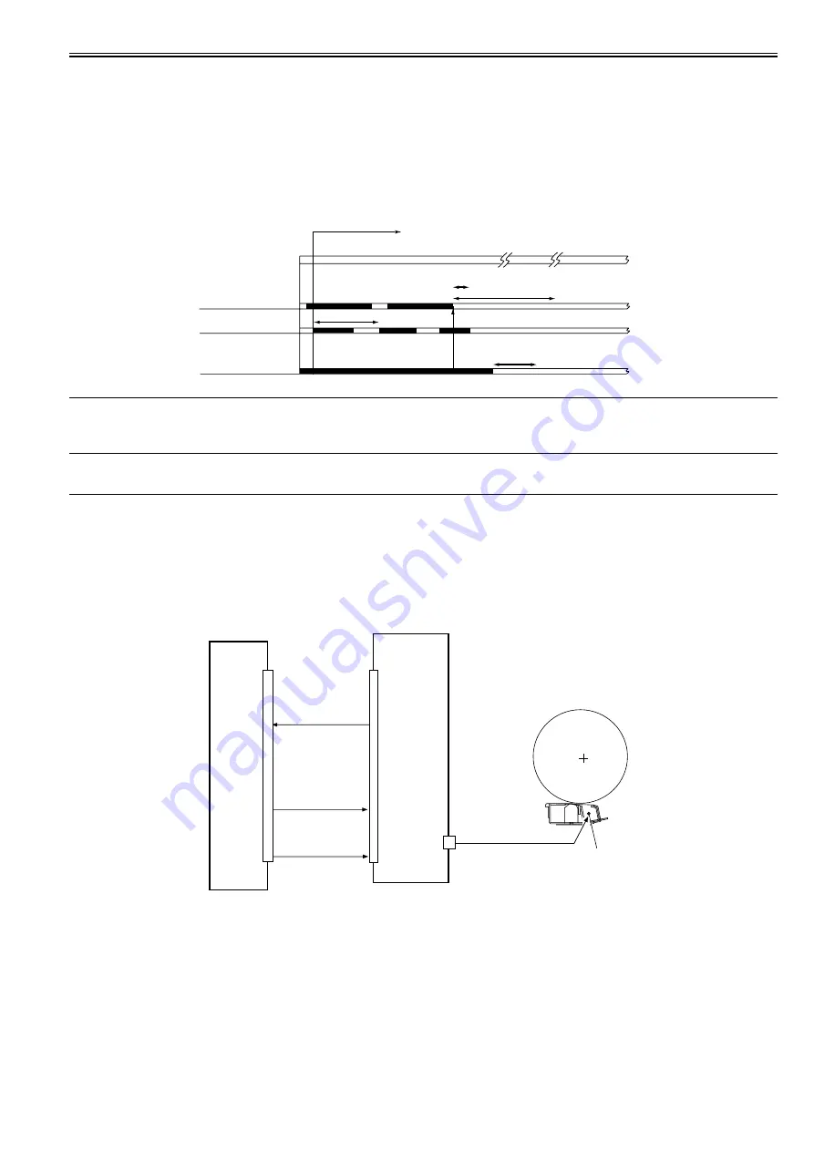
Toner Supply Sequence
The toner inside the developing assembly is monitored by the developing assembly toner level sensor (TS1); when the toner inside the developing assembly falls
below a specific level, the developing assembly toner level signal goes '0' so that the DC controller PCB recognizes it.
If the DC controller PCB detects the developing assembly toner level signal for 0.3 sec or more, it generates the hopper motor drive signal so that the hopper as-
sembly will start supplying toner.
When the toner inside the developing assembly reaches a specific level and, as a result, the developing assembly toner level signal remains '1' for 0.7 sec or more,
the hopper supply motor stops.
When the toner inside the hopper drops below a specific level, the hopper toner level detection signal goes '0'. If the signal remains '0' when the toner supply motor
has been turned on and off 20 times after the detection of the signal state by the DC controller, the machine issues a message of bottle exchange.
Total rotating time reaches 60 seconds after the toner sensor in the developing assembly senses no toner, the machine issues a method of exchanging bottles and
stops the ongoing printing operation.
When the toner bottle is replaced, the hopper supply motor and the stirring motor are turned on, and the developing assembly inside toner level detection signal
goes '1', the machine resets the message of bottle exchange and resumes printing.
F-7-26
ERROR CODE:
E020-0000
Indicated while the output of the inside hopper toner level sensor (TS2) points to the presence of toner and the output of the developing assembly toner level sensor
(TS1) inside the developing assembly points to the absence of toner for 120 sec or more.
7.8 Transfer Mechanism
7.8.1 Transfer Charging Mechanism
7.8.1.1 Overview
0015-4502
iR5065 / iR 5055 / iR5075 / / /
The following items are associated with the transfer charging control system:
1. controlling the DC bias constant current
2. controlling the output to suit the environment (fuzzy control)
The following shows the construction of the transfer charging control system:
F-7-27
The following signals are associated with the transfer charging control mechanism:
[1] Transfer charging leakage detection signal; when the current is too high or too low, '0'
[2] Transfer charging current control signal; used to control the transfer current generated by the high-voltage PCB
[3] High-voltage remote signal; turns on/off the transfer current output
7.8.1.2 Controlling the Output to Suit the Environment (fuzzy control)
0015-4503
iR5065 / iR 5055 / iR5075 / / /
The transfer charging current is optimized to suit the environment (i.e., reading of the environment sensor).
Toner supply sequence start
Toner supply
Hopper supply motor
(M10)
Developing assembly
toner level sensor (TS1)
Inside hopper
toner level sensor (TS2)
Supply
Supply
If 120 sec or more,
'020-0000' is indicated
total activation (ON) time of hopper
stirring motor reaching 60 sec, message of
method of exchanging bottles -> print suspension.
1 cycle (5 sec max.)
toner supply motor driven for 20 cycles,
message of exchanging bottles.
DC controller PCB
High-voltage PCB
HVT_TRANSFER [2]
TRANSFER-LEAK-
DETECT [1]
Transfer charging wire
HVT-REMOTE [3]
J4502
J102A
Summary of Contents for imageRUNNER 5055 series
Page 1: ...Feb 26 2007 Service Manual iR5075 5065 5055 Series ...
Page 2: ......
Page 6: ......
Page 27: ...Chapter 1 Introduction ...
Page 28: ......
Page 30: ......
Page 52: ......
Page 53: ...Chapter 2 Installation ...
Page 54: ......
Page 98: ...Chapter 2 2 42 ...
Page 99: ...Chapter 3 Basic Operation ...
Page 100: ......
Page 102: ......
Page 108: ......
Page 109: ...Chapter 4 Main Controller ...
Page 110: ......
Page 112: ......
Page 129: ...Chapter 5 Original Exposure System ...
Page 130: ......
Page 162: ......
Page 163: ...Chapter 6 Laser Exposure ...
Page 164: ......
Page 166: ......
Page 172: ......
Page 173: ...Chapter 7 Image Formation ...
Page 174: ......
Page 178: ......
Page 210: ......
Page 211: ...Chapter 8 Pickup Feeding System ...
Page 212: ......
Page 263: ...Chapter 9 Fixing System ...
Page 264: ......
Page 268: ......
Page 307: ...Chapter 10 External and Controls ...
Page 308: ......
Page 312: ......
Page 321: ...Chapter 10 10 9 F 10 8 ...
Page 345: ...Chapter 11 MEAP ...
Page 346: ......
Page 348: ......
Page 389: ...Chapter 12 RDS ...
Page 390: ......
Page 392: ......
Page 399: ...Chapter 13 Maintenance and Inspection ...
Page 400: ......
Page 402: ......
Page 411: ...Chapter 14 Standards and Adjustments ...
Page 412: ......
Page 440: ......
Page 441: ...Chapter 15 Correcting Faulty Images ...
Page 442: ......
Page 444: ......
Page 470: ......
Page 471: ...Chapter 16 Self Diagnosis ...
Page 472: ......
Page 474: ......
Page 493: ...Chapter 17 Service Mode ...
Page 494: ......
Page 496: ......
Page 552: ......
Page 553: ...Chapter 18 Upgrading ...
Page 554: ......
Page 556: ......
Page 572: ...Chapter 18 18 16 F 18 29 2 Click Start F 18 30 3 When the session has ended click OK ...
Page 587: ...Chapter 18 18 31 F 18 59 2 Select the data to download F 18 60 3 Click Start ...
Page 589: ...Chapter 19 Service Tools ...
Page 590: ......
Page 592: ......
Page 595: ...Feb 26 2007 ...
Page 596: ......


