background image

58

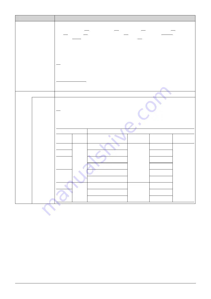
OSD Menu

Item

Setting Options (underline indicates factory default)

Various Function

Displays the function list to execute functions.

Monochrome (On, Off), Blue Only (On, Off), Red Off (On, Off), Green Off (On, Off), Blue Off 
(On, Off), Banner (On, Off)

*

1

, Function Guide (On, Off)

*

2

, OSD Position (Mode 1, Mode 2)

*

3

OSD Size (Large, Small)

*

4

, Backlight Scan (High, Low, Off)

*

1


Banner

When "Banner" is set to "Off", the banner is displayed only when you press the jog dial while OSD is 
closed.
*

2


Function Guide

On

: You can display the list of functions assigned to an F button on the video display by pressing the 

jog dial while OSD is closed.

Off

: Function guide is not displayed.

*

3


OSD Position

Mode 1 (4096x2160)

: OSD is displayed in a 4096x2160 area.

Mode 2 (3840x2160)

: OSD is displayed in a 3840x2160 area.

*

4


OSD Size

: The size of the OSD menu can be selected from "Large" and "Small".

Camera Link

Sets the functions to link with Cinema EOS System cameras.

Adjustment

Sets whether or not to link to the camera's image quality setting when "Canon Log" is selected for 
"Picture Mode".

On, Off

When "Color Gamut/Gamma", "Color Temperature", and "Color Range" are all set to "On", the 
following settings are configured.

Parameter of Cinema EOS System and DP-V2410

Cinema EOS System

DP-V2410

Color

Space

Gamma

Color Gamut

Gamma

Color 

Temperature

Color Range

BT.709

Canon 

Log

ITU-R BT.709

Canon Log

D65

Automatic

BT.2020

ITU-R BT.2020

D65

Cinema

Gamut

Cinema Gamut to 709

D65

Cinema Gamut to DCI-P3

DCI-P3

DCI-P3+

DCI-P3+ to 709

D65

DCI-P3+ to DCI-P3

DCI-P3

BT.2020

Canon 

Log 2

ITU-R BT.2020

Canon Log 2

D65

Cinema

Gamut

Cinema Gamut to 709

D65

Cinema Gamut to DCI-P3

DCI-P3

Summary of Contents for DP-V2410

Page 1: ...play Before use be sure to read this guide including the safety and handling precautions Reading this guide will help you learn to use the video display properly Store this guide safely so that you can use it in the future English ...

Page 2: ...ning on the Power 17 Turning on the Power of the Main Unit 17 Operating the Video Display 18 Operating the jog dial 18 Basic operations to use the OSD menu 18 Adjusting Image Quality While Viewing the Entire Image 20 Temporarily Saving Parameters Anchor Point Setting 21 Calibration without a PC 22 Export Import 23 Set Date Time 25 Inputting Characters 25 Using the Function F Buttons 26 Using the C...

Page 3: ...Information 65 Main specifications Performance 66 Dimensions 67 Appendix 68 Supported Signal Format 68 Image Frame Display 79 Input Signals and Adjustable Setting Item 82 Error Messages 83 Troubleshooting 85 Software Used in This Product 87 Index 89 ...

Page 4: ...dicates reference information CAUTION Indicates an item you must observe Trademarks HDMI HDMI logo and High Definition Multimedia Interface are trademarks or registered trademarks of HDMI Licensing LLC in the U S and other countries VESA is a registered trademark or trademark of Video Electronics Standards Association in the U S and other countries Other product and company names herein are tradem...

Page 5: ...31 330 5000 For the customers in Canada CAN ICES 3 A NMB 3 A For the customers in Europe This product may cause interference if used in residential areas Such use must be avoided unless the user takes special measures to reduce electromagnetic emissions to prevent interference to the reception of radio and television broadcasts CANON INC 30 2 Shimomaruko 3 chome Ohta ku Tokyo 146 8501 Japan CANON ...

Page 6: ...ge due to aging About Temporary Screen burn in If a stationary image is displayed for a prolonged period screen burn in may occur where you see remnants of what was displayed This is a characteristic of LCD and is not a failure However this is only temporary and will disappear when playing video About the LCD screen The screen is produced using extremely high precision manufacturing techniques wit...

Page 7: ...ge the LCD panel The screen may be scratched if wiped too hard with a cleaning cloth with foreign particles attached When the screen is extremely dirty wipe with soft cloth such as cleaning cloth or eye glasses cleaning cloth moistened with water diluted neutral detergent Use a blower to remove dust from the surface of the screen Wipe dirt on cabinet with a soft cloth If the screen is very dirty u...

Page 8: ...proxy ACES 1 0 Equipped with functions to assist shooting and video checking including Wave Form Monitor Vector Scope Screen Capture Zoom and False Color Supports gamma equivalent to CRT standardized by ITU R BT 1886 A color grading controller Element Tk made by Tangent Wave Ltd external sensor or USB memory can be connected to the USB port Separately sold Display Controller CL 01 can be connected...

Page 9: ...es the selection frame within the OSD menu changes the settings up down left right rotation and determines press the selection 18 RESET button Resets the items to be adjusted using the slider and entered characters 18 8 Power button Turns power On Off 17 9 Power indicator Displays the status of the main unit The brightness of the power indicator can be set from Off or 1 dark to 5 brightest 62 Even...

Page 10: ...ction for the provided AC power supply cord 17 CAUTION When connecting an external sensor for calibration to the USB port cable length must not exceed 3 m Otherwise communication error may occur and correct calibration may not be possible For safety do not connect any connector that may have excessive voltage to the terminal of the video display when connecting peripheral devices Pass through SD S...

Page 11: ... You can attach the protection panel to protect the screen when carrying the video display or when using it outdoors 1 Unscrew the four screws on the front face Use a 1 5 mm hexagonal key Do not lose the removed screws Do not use these screws for other purposes 2 Place the protection panel by aligning its corners with the screw holes 67 Take care when attaching the panel in order to avoid damaging...

Page 12: ...on a soft cloth or cushioning material that is larger than the display 2 Remove four fixing screws Do not lose the removed screws Do not use these screws for other purposes Attaching 1 Place the display with the screen facing down on a soft cloth or cushioning material that is larger than the display 2 Align the position of the stand and screw hole on the video display Alight the convex part of th...

Page 13: ...se screws that fit the screw holes The screw hole size is shown below Screw hole 4 4 5 CAUTION When securing the main unit to a table or desk please ensure a table or desk is strong enough to carry the weight of the main unit It is recommended to obtain assistance from another person when performing this step Avoid touching the screen during this step as it may damage it ...

Page 14: ...increase causing a failure or overheating In order to maintain the operating temperature condition of the video display 0 C to 40 C make a space of at least 1U 4 4 cm above and below and at least 4 cm space from its back Make a sufficient space from peripheral equipment secure vents or install a ventilation fan When installing the video display on a wall make sufficient space from the wall so that...

Page 15: ...e these are connected correctly as indicated by the icons Display area icon SDI IN terminal 3G SDI RAW To input 3G SDI RAW signals with a frame rate of 30 00 P or smaller can be input using one input in Input A D Signals with a frame rate over 30 00 P require two inputs either Input A and Input B or Input C and Input D When the frequency is 30 00P or less When the frequency is over 30 00P Input A ...

Page 16: ... terminal HDMI input terminal CAUTION Use a HDMI cable with the High Speed logo that complies with the HDMI standard When a non compliant HDMI standard cable is used the video display may not work normally for example a video becomes choppy or nothing is displayed ...

Page 17: ... Press the power supply button at the front The power indicator lights green CAUTION When using the provided power plug adapter PU 01 be sure to connect the ground terminal to the ground Use a 2 m or shorter DC cord that can bear an electric current of at least 10 A When a cable longer than 2 m is used the video display may not work normally for example a video becomes choppy and nothing is displa...

Page 18: ...are described below MENU button Opens closes the OSD menu or moves up one level in a menu RESET button Resets the items to be adjusted using the slider and entered characters Jog dial Up down left right rotation Used to move to a different item and change settings Press Confirms settings or moves the selection frame up down 1 level Basic operations to use the OSD menu This section describes basic ...

Page 19: ...he main menu on the top screen and then press the MENU button to exit the menu Note Press the RESET button to return Contrast Brightness Chroma Sharpness Power Saturation Offset and Slope to the factory default during adjustment In User 1 7 mode where you are performing calibration the setting returns to the value after calibration instead of the factory default To adjust image quality warming up ...

Page 20: ...djusting Gain R G B Bias R G B under Color Temperature You can adjust RGB all at once or individually when the slider for adjusting Gain R G B and Bias R G B are displayed 1 Switch the guide in the upper right area of the slider screen using the jog dial The indication changes to RGB R G and B 2 When adjustments are completed press the jog dial The screen returns to the original OSD menu Adjusting...

Page 21: ...nchor Adjustment using the jog dial and press the dial to determine the selection When the confirmation screen appears select OK The parameter is saved and sets anchor point 4 Adjust the image quality again and press the RESET button on the video display Press the RESET button to return to each saved anchor point Current value Last used value Anchor point Note Executing Reset under Adjustment or R...

Page 22: ...l of the video display select OK and execute initialization 5 Place the universal measuring probe pointing at the center of the video display Set the mode dial of the universal measuring probe to MEAS and place the probe as shown below according to the displayed content Press the jog dial of the video display select OK and execute calibration Konica Minolta Universal Measuring Probe CA 310 support...

Page 23: ...o the USB port of the main unit LUT Import 39 LUT can be imported except when ACESproxy is selected for Picture Mode or ACESproxy is selected for Color Gamut 1 Press the MENU button to open the OSD menu 2 Select Adjustment Detail Settings LUT Import using the jog dial 3 Select the file using the jog dial In the Filename field search and display a file with extension clut in the root folder 4 Selec...

Page 24: ...tion to save the file to be imported Select Filename In Settings select All or Main Menu Name Select Execute When the confirmation screen appears select OK Import starts Note After export to User 1 3 you can select the configurations at startup from User 1 3 in Power on Setting in System Settings 64 Exporting Importing CDL Parameters 39 1 Press the MENU button to open the OSD menu 2 Select Adjustm...

Page 25: ...is function to specify a channel name a display name or filename 1 Press the MENU button to open the OSD menu 2 The character input screen appears automatically when character input is required Move the selection frame to the location to enter characters using the jog dial or rotation 3 Select characters using the jog dial or rotation The following characters can be selected Press buttons to displ...

Page 26: ... F1 to F8 3 Select the name of the button using the jog dial and press the jog dial to determine the selection The selection frame moves to next OSD menu level 4 Select the function to assign using the jog dial See Display Function or Display Function CDL 61 for the available functions 5 Press the jog dial to determine the selection The setting is confirmed Reference Select Function Settings Vario...

Page 27: ...he following content is assigned to channel buttons on the video display by factory default CH CH1 CH2 CH3 Input Configuration 3G HD SDI HDMI 3G SDI RAW Select Input Signal Automatic Automatic Automatic Format Automatic Automatic Automatic Internal Sync Off Off Off Channel Name Blank Blank Blank Picture Mode ITU R BT 709 ITU R BT 709 Canon Log Color Range Automatic Automatic Automatic Checking Sig...

Page 28: ...ma HDR Range IDT ODT ODT Surround Color Range CDL CDL Preset Power Saturation Offset Slope CDL Bypass Detail Settings CDL Export CDL Import CDL Preset Name Anchor CDL Reset CDL Detail Settings Boost Contrast LUT Import LUT Name LUT Delete 2020 Constant Luminance 2020 Gamut Mapping Calibration Copy Picture Mode Picture Mode Name Anchor Adjustment Reset ...

Page 29: ...Input Signal Format Internal Sync Channel Name Picture Mode Color Range Display Settings 45 Screen Scaling Zoom Scaling Method Frame Hold Background Color I PsF I P Conversion PsF Film Cadence Audio Settings 48 SDI Group CH L R SDI CH L R HDMI Volume Audio Switch Select Input ...

Page 30: ...tion V Position Safety Zone Marker 1 2 Enable Aspect Ratio Area Size Rate Width dot Height dot Shape Line Width Line Color Line Brightness H Position V Position Area Marker Enable H Position V Position Width dot Height dot Mask Line Line Width Line Color Line Brightness Center Marker Enable Size Line Width Line Color Line Brightness ...

Page 31: ...g 2 Off Monochrome Frequency Range Color False Color Screen Capture Capture Frame Hold Capture Source Playback File Finish Playback File Time Code Enable Type Size Position Wave Form Monitor Enable Select Signal Display Type Select Line Position Guide Standard Level High Standard Level Low Color Vector Scope Enable Target Position ...

Page 32: ...nt Color Gamut Gamma Color Temperature Color Range Display Color Gamut Fan Camera Information System Settings 60 Network Language Function Channel Button Display Function Display Function CDL Display Channel Display Name Date Time Power Indicator Brightness Display Button LED Compatible Settings Firmware Update Protect Settings Password Protect Target Protect Fan Settings Fan Control Fan Stop Expo...

Page 33: ...te I P PsF SDI Payload ID Video Standard Sampling Structure Bit Depth Picture Rate Scanning Method Link Number Pixel Encoding Color Depth Matrix RGB Range System Information 65 Display Model Name Display Serial No Display Firmware Ver Display Usage Time Display IP Address Display Subnet Mask Display MAC Address ...

Page 34: ... Boost Contrast is On Contrast BOOST is displayed 0 to 1500 When Boost Contrast in Detail Settings is set to On the settable range is shown below 1500 to 4000 Brightness Adjusts the black level of the image Increments of 1 500 to 500 Chroma Adjusts the color saturation of the image color depth Increments of 1 0 to 2000 Sharpness Adjusts the sharpness of the image Increments of 1 0 to 100 Backlight...

Page 35: ...I P3 Color gamut compliant to each standard Native Color gamut that can be displayed by this video display Cinema Gamut to 709 Cinema Gamut to 2020 Cinema Gamut to DCI DCI P3 to 709 DCI P3 to DCI DCI P3 to 709 ITU R BT 2020 to 709 Modes where the color gamut is converted to monitor Cinema Gamut DCI P3 BT 2020 and DCI P3 videos recorded by the CINEMA EOS SYSTEM EOS C500 C500PL and C300 Mark II ACES...

Page 36: ... 2 6 ITU R BT 1886 Canon Log Canon Log HDR Canon Log 2 Canon Log 2 HDR SMPTE ST 2084 User LUT 1 8 Adobe RGB 2 2 2 35 2 4 2 6 ITU R BT 1886 User LUT 1 8 Canon Log User 1 7 SMPTE C 2 2 2 35 2 4 2 6 ITU R BT 1886 Canon Log Canon Log HDR SMPTE ST 2084 User LUT 1 8 EBU 2 2 2 35 2 4 2 6 ITU R BT 1886 Canon Log Canon Log HDR SMPTE ST 2084 User LUT 1 8 ITU R BT 709 ITU R BT 2020 2 2 2 35 2 4 2 6 ITU R BT ...

Page 37: ...m value 4000 nit is specified part exceeding 4000 nit is clipped and part up to 4000 nit is assigned to the dynamic range of the video display Although the brightness in appearance lowers you can check the dynamic range up to 4000 nit When 1000 nit is specified part exceeding 1000 nit is clipped and part up to 1000 nit is assigned to the dynamic range of the video display The brightness of the vid...

Page 38: ...l 1023 10 bit 4095 12 bit Limited 1 16 235 Limits the black and white range Black level 64 10 bit 256 12 bit White level 940 10 bit 3760 12 bit Limited 2 16 255 Limits the black range Black level 64 10 bit 256 12 bit White level 1023 10 bit 4095 12 bit Note Setting is disabled when ACESproxy is selected for Picture Mode or ACESproxy is selected for Color Gamut Operations when Automatic is selected...

Page 39: ...L 1 CDL 15 All File Type CCC CDL Execute CDL Import Imports CDL parameters Filename Select a filename CDL Preset CDL 1 CDL 15 Execute CDL Preset Name You can specify the name of preset mode within 16 one byte characters including alphabetical characters numbers and symbols Anchor CDL You can temporarily save parameters for Power Saturation Offset and Slope and recover the values anchor point setti...

Page 40: ... of 0 001 x 0 260 to 0 360 0 313 y 0 260 to 0 360 0 329 Color Gamut Sets the color gamut SMPTE C EBU ITU R BT 709 ITU R BT 2020 Adobe RGB DCI P3 Gamma Sets the target gamma 2 2 2 35 2 4 2 6 ITU R BT 1886 Start Performes calibration Note When Luminance is set to high brightness it may be calibrated beyond the brightness adjustment range and set lower than the target value depending on the Color Tem...

Page 41: ... 313 0 313 y 0 329 0 329 0 329 0 329 0 329 Gain R G B 1023 1023 1023 1023 1023 Bias R G B 0 0 0 0 0 Gamma 2 2 2 35 2 2 2 2 2 2 Color Gamut SMPTE C EBU ITU R BT 709 ITU R BT 2020 Adobe RGB Color Range Automatic Automatic Automatic Automatic Automatic IDT ODT ODT Surround CDL Preset CDL 1 CDL 2 CDL 3 CDL 4 CDL 5 Boost Contrast Off Off Off Off Off 2020 Constant Luminance Non constant Luminance Non co...

Page 42: ...23 1023 1023 1023 Bias R G B 0 0 0 0 Gamma 2 6 2 2 Canon Log Color Gamut DCI P3 ITU R BT 709 ITU R BT 709 ACESproxy Color Range Automatic Automatic Automatic Automatic IDT Automatic Automatic ODT DCI P3 DCI P3 ODT Surround Dark Surround Dark Surround CDL Preset CDL 6 CDL 7 13 CDL 14 CDL 15 Boost Contrast Off Off Off Off 2020 Constant Luminance Non constant Luminance Non constant Luminance Non cons...

Page 43: ... Input A D or dual input Dual Input A B or C D onto the center of the screen Note For HDMI the setting is fixed to Automatic For SD SDI only Single Input A D can be selected For Dual Input only 3G SDI RAW can be selected Format Sets the color format and gradation SDI Signal Automatic 4 2 2 YCbCr 10 bit 4 2 2 YCbCr 12 bit 4 4 4 YCbCr 10 bit 4 4 4 YCbCr 12 bit 4 4 4 RGB 10 bit 4 4 4 RGB 12 bit 4 4 4...

Page 44: ...disabled when ACESproxy is selected for Picture Mode or ACESproxy is selected for Color Gamut Operations when Automatic is selected are described below When HDMI is selected Full 0 255 or Limited 1 16 235 is set automatically depending on HDMI signal information When DCI P3 is selected for Picture Mode or DCI P3 Cinema Gamut to DCI or DCI P3 to DCI is selected for Color Gamut Full 0 255 is set Whe...

Page 45: ...rizontal dimensions 1920x1080 3840x2160 Automatic Enlarges to full screen 1920x1080 3840x2160 Note When Peaking or False Color is On the magnification is up to 200 even if Automatic is selected Zoom When the resolution is 4096x2160 or 3840x2160 the enlarged image is displayed at the center of the screen or at the position selected screen of a 4 screen layout Center Top Left Top Right Bottom Left B...

Page 46: ...Color is set to On Background Color Sets the color of the black band to check the boundary of the black band and video image White Gray Off I PsF Defines how the interlace signal or PsF signal is displayed Automatic Automatically determined based on payload and displayed If there is no payload the signal is displayed as an interlace signal Interlace Displayed as an interlace signal PsF Displayed a...

Page 47: ...wn processed interlaced signal input 2 3 Displays progressive image after conversion for 2 3 pulldown processed interlaced signal input 2 3 3 2 Displays progressive image after conversion for 2 3 3 2 pulldown processed interlaced signal input Off Does not perform film cadence mode progressive conversion Note This can be set only when I P Conversion is set to Image Priority ...

Page 48: ...io to be output from the two channels L R of the headphone respectively The options differ according to the SDI Group setting When CH1 CH8 is selected for SDI Group CH1 CH8 When CH9 CH16 is selected for SDI Group CH9 CH16 CH L R HDMI Sets the audio to be output from the two channels L R of the headphone respectively CH1 CH8 Volume Sets the volume 0 to 100 30 Audio Switch Sets the stereo output L R...

Page 49: ...n of Playback File under Screen Capture When a Test Pattern is displayed Enable Switches the aspect marker On Off On Off Mask Switches the mask color Mask is the blanking area outside the range of the marker Black Half 50 gray Off Turns mask off Aspect Ratio Sets the aspect ratio of the aspect marker 16 9 15 9 14 9 13 9 4 3 2 39 1 2 35 1 1 896 1 1 85 1 1 66 1 Variable The aspect ratio can be enter...

Page 50: ...atio Sets the aspect ratio of the safety zone marker 16 9 15 9 14 9 13 9 4 3 2 39 1 2 35 1 1 896 1 1 85 1 1 66 1 Variable The aspect ratio can be entered as a numeric value when you select Variable 0 01 1 increments The grayed out slider becomes active and can be used to set the aspect ratio 1 00 1 to 3 00 1 1 78 1 Note When Area Size is set to Variable dot you cannot select Aspect Ratio Area Size...

Page 51: ...one marker line Thick Normal Thin Line Color Sets the color of the safety zone marker line White Red Green Blue Yellow Cyan Magenta Line Brightness Sets the brightness of the safety zone marker line High Low H Position Adjusts the marker horizontal position with the set aspect and size 65 to 65 0 V Position Adjusts the marker vertical position with the set aspect and size 35 to 35 0 ...

Page 52: ...Sets the start position x coordinate to draw the rectangle in increments of 2 0 to 4086 240 V Position Sets the start position y coordinate to draw the rectangle in increments of 2 0 to 2150 120 Width dot Sets the width of the rectangle in increments of 2 10 to 4096 240 Height dot Sets the height of the rectangle in increments of 2 10 to 2160 120 Mask Switches the mask color in the marker Black Ha...

Page 53: ...White Red Green Blue Yellow Cyan Magenta Line Brightness Sets the brightness of the center marker line High Low Grid Marker Grid Marker is marker used to check the horizontal and vertical position Note Grid Marker is not displayed when an enlarged image is displayed Enable Switches the grid marker On Off On Off Distance Sets the horizontal and vertical line distance 160 dots 240 dots 320 dots Line...

Page 54: ... color to be used White Red Green Blue Yellow Cyan Magenta False Color When set to On different colors are displayed according to video s brightness level so that you can check the exposure condition easily On Off Below are details of the chart Numbers indicate the level of Y signals Red Orange Light orange Yellow Light gray Medium gray Dark gray Blue Blue purple Light purple Purple 1023 940 876 8...

Page 55: ...e Selects the type VITC LTC Size Selects the size Large Small Position Selects the display position Top Left Top Right Bottom Left Bottom Right Wave Form Monitor Configures various settings for the wave form monitor On the wave form monitor the horizontal axis shows the horizontal resolution of the video and the vertical line shows the signal level 254 4 0 50 100 0 Signal level Horizontal resoluti...

Page 56: ...hite Red Green Blue Yellow Cyan Magenta Default value of each signal is shown below Y White Cb White Cr White R Red G Green B Blue Standard Level High Standard Level Low Selects the standard level White Red Green Blue Yellow Cyan Magenta Default value of each standard level is shown below Standard Level High Magenta Standard Level Low Cyan Vector Scope Configures various settings for the vector sc...

Page 57: ...SDI Group 2CH CH9 CH10 4CH CH9 CH12 6CH CH9 CH14 8CH CH9 CH16 Channel Number HDMI Sets the number of channels displayed when HDMI signal is input 2CH CH1 CH2 4CH CH1 CH4 6CH CH1 CH6 8CH CH1 CH8 Peak Hold When set to On one second of audio signal at the peak is kept On Off Standard Level Sets the standard level 40 to 0 20 Test Pattern Sets the test pattern built into the main unit White Gray 20 Bla...

Page 58: ...60 area Mode 2 3840x2160 OSD is displayed in a 3840x2160 area 4 OSD Size The size of the OSD menu can be selected from Large and Small Camera Link Sets the functions to link with Cinema EOS System cameras Adjustment Sets whether or not to link to the camera s image quality setting when Canon Log is selected for Picture Mode On Off When Color Gamut Gamma Color Temperature and Color Range are all se...

Page 59: ... cameras and Canon professional use video cameras At a room temperature 25 C the fan remains off for approximately one minute when the AC power supply is used and ten minutes when the DC power supply is used Select the type of power supply according to the purposes If the temperature inside the main unit increases while the fan is off the message Fan will be rotated as the temperature is high is d...

Page 60: ...y Function CDL Sets the function to assign to the F buttons of the main unit Select an F button and assign a function from the following list The factory defaults for the main unit F buttons is as follow Normal mode F1 Contrast F2 Brightness F3 Time Code On Off F4 WFM VEC On Off F5 Audio Level Meter On Off F6 Zoom On Off F7 Hide OSD On Off F8 Boost Contrast On Off CDL mode F1 CDL R On Off F2 CDL G...

Page 61: ...I P3 to 709 ITU R BT 2020 to 709 ACESproxy User LUT 1 8 Gamma 2 2 2 35 2 4 2 6 ITU R BT 1886 Canon Log Canon Log HDR Canon Log 2 Canon Log 2 HDR SMPTE ST 2084 User LUT 1 8 HDR Range CDL CDL Preset CDL SOP Sat Channel Settings Channel UP Channel DOWN Select Input Signal Automatic 4K Input Single Input Dual Input Display Settings Screen Scaling Native Input Resolution 200 Automatic Frame Hold On Off...

Page 62: ...ied to Enable under the currently selected Marker Preset Display Channel Sets the channel to assign to the CH button on the display Select a CH button and register a channel number A list of settings under the menu Channel Settings 43 is displayed Display Name Sets the name of the main unit You can input up to 16 alphanumeric characters Date Time Sets the year month date hour minute Power Indicato...

Page 63: ... stopping in order to prevent the internal temperature from increasing when the fan is stopped manually On Off Fan Stop The fan can be stopped manually when Fan Control is set to On The fan noise can be made silent when the video display is used during shooting or when silence is necessary On Off Note If the message Invalid operation due to high temperature is displayed the fan cannot be stopped e...

Page 64: ...ault is dinfo_dpv2410 dat You can change the name of the file to be exported to the USB memory within 16 one byte characters including alphabetical characters numbers and symbols Execute Performs export Import Target Specify the destination to save the file to be imported USB User 1 3 Filename Displays files with the extension dat so you can select from among them Settings All Adjustment Channel S...

Page 65: ...ink Number CH1 3G HD SD SDI 3G SDI Level A 4K Input Automatic 4096x2160 24 00P 89 C3 46 01 3G SDI 4 4 4 4 GBRA 10 bit 24 00 Progressive Progressive Transport Picture Single Link_1 Channel Input Configuration Select Input Signal Resolution Picture Rate I P PsF Pixel Encoding Color Depth Matrix RGB Range CH4 HDMI Automatic 4096x2160 60 00P 4 2 2 YCbCr 10 bit ITU R BT 709 Full When a content is graye...

Page 66: ...erature and humidity 20 40 C 4 104 F 20 85 RH no condensation 41 60 C 105 140 F 20 30 RH no condensation Pressure 700 1060 hPa Dimensions width x height x depth Including stands Approx 594 399 187 mm 23 4 15 7 7 4 in Main unit only excluding protrusions Approx 594 378 106 mm 23 4 14 9 4 2 in Weight Approximately 12 kg 26 4 lb Mounting Hole Pitch VESA standard 100 x 100 mm 3 9 x 3 9 in Interface In...

Page 67: ... 4 100 3 9 106 4 2 187 7 4 493 19 4 355 4 14 0 61 2 4 41 1 6 40 1 6 47 5 1 9 10 0 4 100 3 9 4 M4 Depth 8 0 3 MAX 4 M4 Depth 7 0 3 MAX 312 12 3 378 14 9 399 15 7 230 9 1 374 14 7 144 5 7 160 6 3 21 0 8 5 0 2 15 0 6 15 0 6 567 6 22 3 4 4 5 0 2 Unit mm inch Front Rear Side Bottom ...

Page 68: ...0x1080P 25 00 Hz 1920x1080PsF 25 00 Hz 1920x1080P 23 98 24 00 Hz 1920x1080PsF 23 98 24 00 Hz 2048x1080i 59 94 60 00 Hz 2048x1080i 50 00 Hz 2048x1080P 29 97 30 00 Hz SMPTE 292 1 SMPTE 428 9 SMPTE 428 19 SMPTE 2048 2 2048x1080PsF 29 97 30 00 Hz 2048x1080P 25 00 Hz 2048x1080PsF 25 00 Hz 2048x1080P 23 98 24 00 Hz 2048x1080PsF 23 98 24 00 Hz 3G SDI Level A x 1 1280x720P 59 94 60 00 Hz 4 4 4 RGB 4 4 4 Y...

Page 69: ...it SMPTE 425 1 SMPTE 274M 4 2 2 YCbCr 12 bit 1920x1080P 25 00 Hz 4 4 4 RGB 4 4 4 YCbCr 12 bit 10 bit 4 2 2 YCbCr 12 bit 1920x1080PsF 25 00 Hz 4 4 4 RGB 10 bit 12 bit 4 4 4 YCbCr 12 bit 4 4 4 YCbCr 10 bit SMPTE 425 1 SMPTE 274M 4 2 2 YCbCr 12 bit 1920x1080P 23 98 24 00 Hz 4 4 4 RGB 4 4 4 YCbCr 12 bit 10 bit 4 2 2 YCbCr 12 bit 1920x1080PsF 23 98 24 00 Hz 4 4 4 RGB 10 bit 12 bit 4 4 4 YCbCr 12 bit 4 ...

Page 70: ...t SMPTE 425 1 SMPTE 2048 2 4 2 2 YCbCr 12 bit 2048x1080P 25 00 Hz 4 4 4 RGB 12 bit 10 bit SMPTE 425 1 SMPTE 428 9 SMPTE 428 19 SMPTE 2048 2 4 4 4 X Y Z 12 bit 4 4 4 YCbCr 12 bit 10 bit SMPTE 425 1 SMPTE 2048 2 4 2 2 YCbCr 12 bit 2048x1080PsF 25 00 Hz 4 4 4 RGB 12 bit 10 bit SMPTE 425 1 SMPTE 428 9 SMPTE 428 19 SMPTE 2048 2 4 4 4 X Y Z 12 bit 4 4 4 YCbCr 12 bit 10 bit SMPTE 425 1 SMPTE 2048 2 4 2 2...

Page 71: ...2 bit 10 bit 4 2 2 YCbCr 12 bit 1920x1080P 25 00 Hz 4 4 4 RGB 4 4 4 YCbCr 12 bit 10 bit 4 2 2 YCbCr 12 bit 1920x1080PsF 25 00 Hz 4 4 4 RGB 4 4 4 YCbCr 12 bit 10 bit 4 2 2 YCbCr 12 bit 1920x1080P 23 98 24 00 Hz 4 4 4 RGB 4 4 4 YCbCr 12 bit 10 bit 4 2 2 YCbCr 12 bit 1920x1080PsF 23 98 24 00 Hz 4 4 4 RGB 4 4 4 YCbCr 12 bit 10 bit 4 2 2 YCbCr 12 bit 2048x1080P 59 94 60 00 Hz 4 2 2 YCbCr 10 bit SMPTE 4...

Page 72: ...X Y Z 12 bit 4 4 4 YCbCr 12 bit 10 bit SMPTE 425 1 SMPTE 372 SMPTE 2048 2 4 2 2 YCbCr 12 bit 2048x1080P 25 00 Hz 4 4 4 RGB 12 bit 10 bit SMPTE 425 1 SMPTE 372 SMPTE 428 9 SMPTE 428 19 SMPTE 2048 2 4 4 4 X Y Z 12 bit 4 4 4 YCbCr 12 bit 10 bit SMPTE 425 1 SMPTE 372 SMPTE 2048 2 4 2 2 YCbCr 12 bit 2048x1080PsF 25 00 Hz 4 4 4 RGB 12 bit 10 bit SMPTE 425 1 SMPTE 372 SMPTE 428 9 SMPTE 428 19 SMPTE 2048 ...

Page 73: ... 25 00 Hz 3840x2160P 23 98 24 00 Hz 3840x2160PsF 23 98 24 00 Hz 4096x2160i 59 94 60 00 Hz 4096x2160i 50 00 Hz 4096x2160P 29 97 30 00 Hz SMPTE 292 1 SMPTE 428 9 SMPTE 428 19 SMPTE 2048 2 4096x2160P 29 97 30 00 Hz 4096x2160PsF 29 97 30 00 Hz 4096x2160P 25 00 Hz 4096x2160PsF 25 00 Hz 4096x2160P 23 98 24 00 Hz 4096x2160PsF 23 98 24 00 Hz 3G SDI Level A x 4 3840x2160P 59 94 60 00 Hz 4 2 2 YCbCr 10 bit ...

Page 74: ... 2 2 YCbCr 12 bit 3840x2160P 23 98 24 00 Hz 4 4 4 RGB 4 4 4 YCbCr 12 bit 10 bit 4 2 2 YCbCr 12 bit 3840x2160PsF 23 98 24 00 Hz 4 4 4 RGB 10 bit 12 bit 4 4 4 YCbCr 12 bit 4 4 4 YCbCr 10 bit SMPTE 425 1 SMPTE 274M 4 2 2 YCbCr 12 bit 4096x2160P 59 94 60 00 Hz 4 2 2 YCbCr 10 bit SMPTE 425 1 SMPTE 428 9 SMPTE 428 19 SMPTE 2048 2 4096x2160i 59 94 60 00 Hz 4 4 4 RGB 4 4 4 YCbCr 12 bit 10 bit 4 4 4 X Y Z ...

Page 75: ...PTE 425 1 SMPTE 2048 2 4 2 2 YCbCr 12 bit 4096x2160PsF 25 00 Hz 4 4 4 RGB 12 bit 10 bit SMPTE 425 1 SMPTE 428 9 SMPTE 428 19 SMPTE 2048 2 4 4 4 X Y Z 12 bit 4 4 4 YCbCr 12 bit 10 bit SMPTE 425 1 SMPTE 2048 2 4 2 2 YCbCr 12 bit 4096x2160P 23 98 24 00 Hz 4 4 4 RGB 12 bit 10 bit SMPTE 425 1 SMPTE 428 9 SMPTE 428 19 SMPTE 2048 2 4 4 4 X Y Z 12 bit 4 4 4 YCbCr 12 bit 10 bit SMPTE 425 1 SMPTE 2048 2 4 2...

Page 76: ... 00 Hz 4 4 4 RGB 4 4 4 YCbCr 12 bit 10 bit 4 2 2 YCbCr 12 bit 3840x2160P 23 98 24 00 Hz 4 4 4 RGB 4 4 4 YCbCr 12 bit 10 bit 4 2 2 YCbCr 12 bit 3840x2160PsF 23 98 24 00 Hz 4 4 4 RGB 4 4 4 YCbCr 12 bit 10 bit 4 2 2 YCbCr 12 bit 4096x2160P 59 94 60 00 Hz 4 2 2 YCbCr 10 bit SMPTE 425 1 SMPTE 372 SMPTE 428 9 SMPTE 428 19 SMPTE 2048 2 4096x2160i 59 94 60 00 Hz 4 4 4 RGB 4 4 4 YCbCr 12 bit 10 bit 4 4 4 X...

Page 77: ...096x2160P 25 00 Hz 4 4 4 RGB 12 bit 10 bit SMPTE 425 1 SMPTE 372 SMPTE 428 9 SMPTE 428 19 SMPTE 2048 2 4 4 4 X Y Z 12 bit 4 4 4 YCbCr 12 bit 10 bit SMPTE 425 1 SMPTE 372 SMPTE 2048 2 4 2 2 YCbCr 12 bit 4096x2160PsF 25 00 Hz 4 4 4 RGB 12 bit 10 bit SMPTE 425 1 SMPTE 372 SMPTE 428 9 SMPTE 428 19 SMPTE 2048 2 4 4 4 X Y Z 12 bit 4 4 4 YCbCr 12 bit 10 bit SMPTE 425 1 SMPTE 372 SMPTE 2048 2 4 2 2 YCbCr ...

Page 78: ...1080P 29 97 30 00 Hz 1920x1080P 25 00 Hz 1920x1080P 23 98 24 00 Hz 2048x1080P 59 94 60 00 Hz 2048x1080P 50 00 Hz 2048x1080P 29 97 30 00 Hz 2048x1080P 25 00 Hz 2048x1080P 23 98 24 00 Hz 3840x2160P 59 94 60 00 Hz 4 4 4 RGB 8 bit 4 4 4 YCbCr 8 bit 4 2 2 YCbC 12 bit 4 2 0 YCbC 12 bit 10 bit 8 bit 3840x2160P 50 00 Hz 3840x2160P 29 97 30 00 Hz 4 4 4 RGB 12 bit 10 bit 8 bit 4 4 4 YCbCr 12 bit 10 bit 8 bi...

Page 79: ... 97 30 00 P 59 94 60 00 P 50 00 P 50 00 P 59 94 60 00 P 59 94 60 00 P 2048x1080 50 00 i 50 00 P 59 94 60 00 i 59 94 60 00 P 23 98 24 00 PsF 47 96 48 00 P 25 00 PsF 50 00 P 29 97 30 00 PsF 59 94 60 00 P 23 98 24 00 P 47 96 48 00 P 25 00 P 50 00 P 29 97 30 00 P 59 94 60 00 P 47 95 48 00 P 47 95 48 00 P 50 00 P 50 00 P 59 94 60 00 P 59 94 60 00 P 3840x2160 50 00 i 50 00 P 59 94 60 00 i 59 94 60 00 P ...

Page 80: ...9 94 60 00 i 59 94 60 00 P 23 98 24 00 PsF 47 96 48 00 P 25 00 PsF 50 00 P 29 97 30 00 PsF 59 94 60 00 P 23 98 24 00 P 47 96 48 00 P 25 00 P 50 00 P 29 97 30 00 P 59 94 60 00 P 47 95 48 00 P 47 95 48 00 P 50 00 P 50 00 P 59 94 60 00 P 59 94 60 00 P Displaying same frame ...

Page 81: ...1920x1080 29 97 30 00 P 59 94 60 00 P 1920x1080 25 00 P 50 00 P 1920x1080 23 98 24 00 P 47 96 48 00 P 2048x1080 59 94 60 00 P 59 94 60 00 P 2048x1080 50 00 P 50 00 P 2048x1080 29 97 30 00 P 59 94 60 00 P 2048x1080 25 00 P 50 00 P 2048x1080 23 98 24 00 P 47 96 48 00 P 3840x2160 59 94 60 00 P 59 94 60 00 P 3840x2160 50 00 P 50 00 P 3840x2160 29 97 30 00 P 59 94 60 00 P 3840x2160 25 00 P 50 00 P 3840...

Page 82: ... Capture 10 Camera Link 11 12 Setting is disabled 1 SD SDI is fixed to Non constant Luminance 2 Cannot be set to Dual Input 3 Fixed to Automatic 4 SD SDI is fixed to 4 2 2 YCbCr 10 bit 5 Fixed to Automatic 6 Only Automatic or 4 4 4 XYZ 10 12 bit can be selected 7 Only Center or Off can be selected 8 Can be set only when I P Conversion is set to Image Priority 9 Can be displayed only on Canon camer...

Page 83: ...r USB memory or delete the content of the memory Failed to write file The USB memory may be defective or protected Check the USB memory LUT Various settings CDL import LUT Import LUT Type is different CDL Import File Type is different Select the correct file format Failed to read file The USB memory may be defective or protected Check the USB memory Failed to import There is an error in the file t...

Page 84: ... the OSD menu move the selection frame to Protect Settings and press the jog dial for approximately 3 seconds CDL Bypass is on When CDL Bypass is turned On you cannot adjust Power Saturation Offset or Slope Invalid Password Enter the correct password USB memory USB memory is not connected Correctly connect the USB memory to the USB port of this main unit Unsupported USB memory Check the USB memory...

Page 85: ... case the message indicating low voltage is not displayed Connect a charged DC power supply or AC power supply The image does not display Set each item in Channel Settings according to input signal 43 There is a blank area when set to 4K Input There may be no input signal Look at the display area icon in the interface area and check that the input area and signal cables are properly connected Sign...

Page 86: ...n does not stop even when Fan under Camera Link is set to On or Fan Stop is set to On The fan does not stop if the internal temperature of the video display is high Configure settings after the internal temperature has lowered The fan may not stop in some conditions for example when used at a high temperature Use the video display at the operating temperature 66 or lower 59 63 You forgot the passw...

Page 87: ...t require its license agreement to be displayed This license agreement is as follows libupnp License Copyright c 2000 2003 Intel Corporation All rights reserved Redistribution and use in source and binary forms with or without modification are permitted provided that the following conditions are met Redistributions of source code must retain the above copyright notice this list of conditions and t...

Page 88: ...e and this permission notice shall be included in all copies or substantial portions of the Software THE SOFTWARE IS PROVIDED AS IS WITHOUT WARRANTY OF ANY KIND EXPRESS OR IMPLIED INCLUDING BUT NOT LIMITED TO THE WARRANTIES OF MERCHANTABILITY FITNESS FOR A PARTICULAR PURPOSE AND NONINFRINGEMENT IN NO EVENT SHALL THE DANIEL VEILLARD BE LIABLE FOR ANY CLAIM DAMAGES OR OTHER LIABILITY WHETHER IN AN A...

Page 89: ...DL Export CDL Import 24 39 Center Marker 53 Channel Name 25 44 Channel Settings 43 Channel UP Channel DOWN 61 Chroma 34 Cinema Gamut to 709 35 Cinema Gamut to 2020 35 Cinema Gamut to DCI 35 Color Bars Test Pattern 57 Color Gamut 35 Color Range 38 44 Color Temperature 35 Compatible Settings 62 Configure an IP Address 60 Contrast 34 Custom xy Color Temperature 35 D Date Time 25 62 DCI P3 34 DCI P3 t...

Page 90: ...SD Menu 18 28 OSD Position 58 OSD Size 58 P Password 63 Peaking 54 Picture Mode 34 PLUGE Test Pattern 57 Power 39 Power Indicator Brightness 62 Power on Setting 64 Protect Settings 63 PsF 46 R Ramp Test Pattern 57 Red Off 58 Red Test Pattern 57 Reset 40 Reset All Settings 64 S Safety Zone Marker 1 2 50 Saturation 39 Scaling Method 46 Bicubic 46 Nearest Neighbor 46 Shape Trace 46 Screen Capture 54 ...

Page 91: ...ex T Test Pattern 57 Time Code 55 U Usage Time 65 USB 9 22 23 User 1 7 34 User LUT 35 36 V Various Function Function Settings 58 Vector Scope 56 VITC 55 W Wave Form Monitor 55 White Test Pattern 57 Z Zoom 45 ...

Page 92: ...SA will have no responsibility Canon USA shall have no responsibility under this limited warranty for use of the Equipment in conjunction with incompatible peripheral equipment and or incompatible software Non Canon brand peripheral equipment and software which may be distributed with or be factory loaded on the Equipment are sold AS IS without warranty of any kind by Canon USA including any impli...

Page 93: ...S EXPENSE FOR SUBSTITUTE EQUIPMENT OR SERVICE STORAGE CHARGES LOSS OR CORRUPTION OF DATA INCLUDING WITHOUT LIMITATION LOSS OR CORRUPTION OF DATA STORED ON THE EQUIPMENT S HARD DRIVE OR ANY OTHER SPECIAL INCIDENTAL OR CONSEQUENTIAL DAMAGES CAUSED BY THE USE MISUSE OR INABILITY TO USE THE EQUIPMENT REGARDLESS OF THE LEGAL THEORY ON WHICH THE CLAIM IS BASED AND EVEN IF CANON USA HAS BEEN ADVISED OF T...

Page 94: ...ftware as to which items Canon Canada will have no responsibility Canon Canada shall have no responsibility under this limited warranty for use of the Equipment in conjunction with incompatible computer equipment peripheral equipment and or incompatible software Non Canon brand peripheral equipment and software which may be distributed with or be factory loaded on the Equipment are sold AS IS with...

Page 95: ...ORAGE CHARGES LOSS OR CORRUPTION OF DATA INCLUDING WITHOUT LIMITATION LOSS OR CORRUPTION OF DATA STORED ON THE EQUIPMENT S HARD DRIVE OR ANY OTHER SPECIAL INCIDENTAL OR CONSEQUENTIAL DAMAGES CAUSED BY THE USE MISUSE OR INABILITY TO USE THE EQUIPMENT REGARDLESS OF THE LEGAL THEORY ON WHICH THE CLAIM IS BASED AND EVEN IF CANON CANADA HAS BEEN ADVISED OF THE POSSIBILITY OF SUCH DAMAGES NOR SHALL RECO...

Page 96: ...weg 59 1185 XB Amstelveen The Netherlands MÉXICO CANON MEXICANA S DE RL DE CV http www canon com mx 52 55 5249 4900 NEW ZEALAND www canon co nz Canon New Zealand Ltd 0800 222 666 within New Zealand only 64 09 489 0300 UNITED KINGDOM www canon co uk Canon UK Ltd CCI Service Centre Unit 130 Centennial Park Borehamwood Hertfordshire WD6 3SE 0844 369 0100 USA CANON U S A INC http pro usa canon com htt...

Reviews: