Cambridge Air Solutions
90
S-Series Technical Manual
10. Suspend the damper motor assembly from
the damper motor support bracket. Turn the
disconnect switch on and turn the blower
service switch to the ”LOCAL” position for
approximately 5 seconds.
IMPORTANT
Do not restrain the drive tube from turning freely.
11. Turn the blower service switch to the ”REMOTE”
position until the damper motor drive tube stops
turning. (Drive tube is now fully retracted).
12. Turn the disconnect switch off. Manually trip the
motor starter overload using the manual trip lever
located on the overload between the overload and
the motor starter.
13. Slide the damper linkage tube into the drive tube
and align the hole in the drive tube with the hole
in the damper linkage tube by manually rotating
the drive tube in 1/2 turn increments until the
5/16” diameter clevis pin can pass through both
parts. Lubrication of the damper linkage tube
may be required. Maintain the damper blades in
the tightly-held, fully closed position during this
adjustment.
14. Turn the disconnect switch on and turn the blower
service switch to the ”LOCAL” position. The
damper will open to the point the upper cam
engages the upper limit switch.
15. Remove the plastic plug from the damper viewport
(located on the exterior side of the heater housing
toward the discharge end). It may be helpful
to place a flashlight inside the heater housing
to observe the damper linkage tube travel to
ultimately rest against the hex shaft.
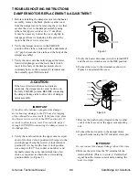
16. Using a deep-well, 1/2” hex socket or nut driver,
turn the upper cam hex nut clockwise in one click
increments until the damper linkage tube rests
against the hex shaft. (Refer to Figure 3. )
IMPORTANT
Damper blades should be snug to avoid fluttering in
the high velocity air stream.
Figure 3
m
CAUTION:
Do not over-drive the damper motor as damage to
the PC board or tripping of the onboard fuse may
result. If the fuse trips, place the blower service
switch in the ”OFF” position for 15 seconds to
allow fuse to reset.
17. Turn the blower service switch to the ”REMOTE”
position and, after the damper motor closes, turn
the disconnect switch off.
18. Reinstall the plastic plug from the damper
viewport and the weather cover push-in plug.
19. Reconnect the wire removed in step 9 to terminal
”G”.
20. Reset the motor starter overload.
21. Verify that both service switches are in the
”REMOTE” position, close the electrical
enclosure door and turn the disconnect switch on.


