Cambridge Air Solutions
86
S-Series Technical Manual
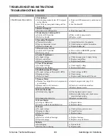
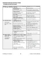
Problem
Possible Cause
Corrective Action
VI. HIGH LIMIT TRIPPED
1. High Limit
a) High limit will not reset
a) Replace high limit.
2. Unit Overfiring
a) Manifold pressure too high
a) Adjust appliance regulator to obtain
temperature rise specified on nameplate.
3. Discharge Damper
a) Damper blades partially closed
b) Defective damper motor
a) Adjust damper stroke length.
b) Replace damper motor.
4. Low Airflow
a) Blower running backwards
b) Belts slipping
c) Blocked intake or discharge
a) Reverse motor direction.
b) Tighten or replace belts.
c) Find and remove obstruction.
5. Temperature Control System
a) Temperature control system does not
modulate
a) See problem VIII (page 86).
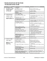
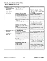
VII. BLOWER RUNS;
UNIT HEATS;
WILL NOT CYCLE
OFF
1. Operating Thermostat
a) Short in thermistor circuit
b) Thermostat located improperly
c) Thermostat differential setting too wide
d) Defective thermostat
a) Check thermistor wiring and/or replace
thermistor.
b1) Thermostat in cold draft-relocate.
b2) Thermostat not satisfied-turn down.
c) Reduce differential setting.
d) Replace thermostat.
2. Burner Service Switch
a) Switch in LOCAL position
a) Place switch in REMOTE position.
3. Auxiliary Control
a) Auxiliary contacts closed
a) Check auxiliary circuit wiring and
contacts.
4. Misunderstood Control System
Operation
a) Control system doesn’t function as
expected
a) Review control system operational
characteristics.
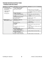
VIII. MODULATING
VALVE DOES NOT
MODULATE;
CONTINUOUS
HIGH FIRE
1. Amplifier (A1014 or A1044 or AD1014)
a) Wire not connected to amplifier terminal
3 or 4. Also terminal 5 on A1044
amplifier
b) Jumper not installed between terminals 2
and 3 of A1014 or AD1014
c) Defective amplifier
a) Reinstall wire.
b) Reinstall jumper.
c) Replace amplifier.
2. Discharge Temperature Sensor
(TS114J or TS144)
a) Discharge Air Temperature Sampling
Tube clogged
b) Open in sensor circuit
c) Sensor cross-wired to amplifier
d) Temperature Control System out of
calibration
a) Clean Discharge Air Temperature
Sampling Tube (page 69).
b) Replace the sensor if the resistance
measured at terminals 1 and 2 on TS114J
sensor exceeds 15,000 Ω 1 and 3 or 2 and
3 on TS144 exceeds 6,000 Ω.
c) Correct wiring terminations.
d) Perform appropriate calibration procedure
(pages 60–62).
TROUBLESHOOTING INSTRUCTIONS
TROUBLESHOOTING GUIDE

