S-Series Technical Manual
13
Cambridge Air Solutions
INSTALLATION INSTRUCTIONS
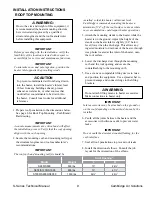
ROOF TOP / THRU WALL MOUNTING
m
WARNING:
Due to the size and weight of this equipment, it
is recommended the heater mounting structure be
reviewed and approved by a qualified structural
engineer and the roof manufacturer before
installing this equipment.
IMPORTANT
Before proceeding with the installation, verify the fea-
sibility of the location selected with respect to acces-
sibility to the equipment for service and maintenance
functions.
IMPORTANT
To minimize snow and rain ingestion, position the
heater inlet opposite the prevailing winds.
m
CAUTION
To prevent contaminated air from being drawn
into the heater, install the heater’s inlet at least 10
feet from any building exhaust, process exhaust,
sewer stacks, or other sources that would allow
contaminants to be drawn into the heater. Consult
local codes for additional references.
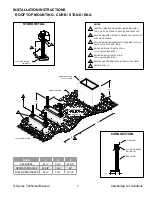
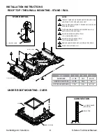
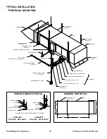
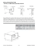
1. Prepare wall penetration to the dimensions below.
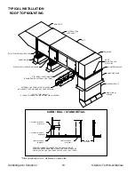
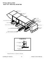
See page 7 for Roof Top/Thru Wall Mounting
Stand/Rail drawing.
IMPORTANT
Accurate measurements are critical and will affect
installation process.
2. Secure the mounting rails per the structural
engineer and roof manufacturer’s
recommendations.
IMPORTANT
The mounting rails should be installed so that the
heater will mount level. Cambridge recommends
mounting the heater a minimum of 24” off the roof
surface in areas where snow accumulation could
impact heater operations
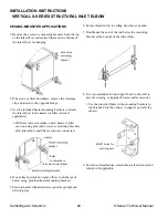
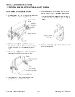
3. Attach the mounting stands to the heater while
the heater is on the ground. Adjust the height
of the stands so the heater inlet is slightly (1/8”
below level) lower than the discharge. This allows
any ingested moisture to drain out of the heater,
through weep holes located at the inlet of the heat-
er, onto the roof surface.
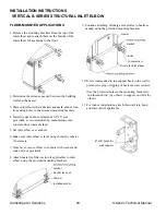
4. Use a crane or comparable lifting device to raise
and position equipment. Use a spreader bar to
prevent damage and connect slings to the lifting
brackets.
m
WARNING:
Do not attach lifting means to heater accessories.
Make connections to heater only.
IMPORTANT
Inlet accessories may be attached on the ground or
on the roof depending on the method chosen by the
installer.
5. Install the wall sleeve to the heater discharge.
6. Install fiberglass insulation in gaps around the wall
opening and wall sleeve. Apply enough material to
accommodate the full thickness of the wall.
7. Install finish trim pieces (by others) to top, sides
and bottom of the wall sleeve on both the inside
and outside wall surfaces.
8. Apply silicone caulk at the joint between the top
of the wall sleeve and the outside wall surface.
Make certain this is a continuous bead and that it
runs the entire width of the wall sleeve. Caulk all
other exposed joints.
9. Seal all roof penetrations to prevent roof leaks.
10. Install the downturn and directional elbows.
Consult the job layout for the orientation of the
elbows.
Weight
Wall Opening*
Model
H
W
S400/S800
550 lbs.
16”
28¼”
S950/S1200/S1600
800 lbs.
18”
45”
S1850/S2200/S3200
1500 lbs.
27½”
50”


