Caliper Life Sciences Twister II User Manual Download Page 140

Appendix A: Software Reference 140

P/N 113564 Rev. 2

Twister II Robot User’s Manual

Caliper Life Sciences, Inc.


Teach Wizard Buttons

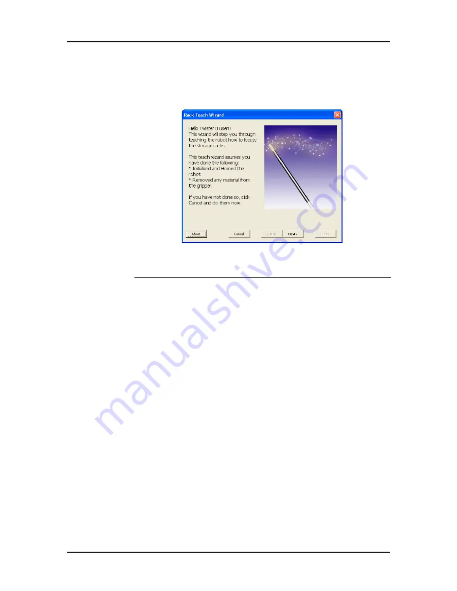
The Teach Wizard windows have the same buttons at the bottom of 
the window that perform the functions described below. 

Figure 113. Teach Wizard Buttons

Option

Definition

Abort

Aborts the act of teaching a position. 

Cancel

Closes the Rack Teach Wizard without saving the 
positions that were taught. 

Back

Returns to the previous window.

Next

Advances to the next window.

Finish

Completes position teaching and closes the 
wizard.

Summary of Contents for Twister II

Page 1: ...Copyright 2001 2006 Caliper Life Sciences Inc All rights reserved P N 113564 Rev 2 User s Manual Twister II Robot...

Page 2: ...s option be new or remanufactured All parts removed from warranted equipment become the property of Caliper Caliper reserves the right to satisfy its warranty obligations in full by refunding the purc...

Page 3: ...hazardous to Caliper personnel Caliper reserves the right to refuse to service the equipment II MICROFLUIDIC CHIPS Caliper warrants that microfluidic chips each a Chip purchased from Caliper by Custo...

Page 4: ...nd money in developing the products purchased with the Program The Program contains Licensor s trade secrets which must be used in confidence You acknowledge and agree that the program is proprietary...

Page 5: ...the laws of the Commonwealth of Massachusetts Any dispute will be resolved in the state and federal courts of the Commonwealth of Massachusetts 9 Severability Should any term of this License Agreemen...

Page 6: ...n this manual may contain typographical errors or technical inaccuracies and is subject to change without notice Modifications may also be made to the product described in this manual at any time Stat...

Page 7: ...estion about a product that is not answered in this manual or if you need assistance regarding this product please contact the Caliper Technical Support Center from 8 00 A M to 8 00 P M Eastern Time M...

Page 8: ...c servicing performed on site by Caliper field service engineers Extended use of the Caliper Technical Support Center Use of a software program for automated remote troubleshooting Software updates Pa...

Page 9: ...or modifications to this equipment not expressly approved by the party responsible for compliance could void the user s authority to operate the equipment REMARQUE Tout changement ou modification app...

Page 10: ...ion AVERTISSEMENT Attention danger potentiel Se reporter la documentation de l utilisateur NOTE A cautionary statement an operating tip or maintenance suggestion may result in instrument damage if not...

Page 11: ...t avoid exposure Risk of eye injury Rayonnement laser viter toute exposition Risque de l sion oculaire Lifting hazard May result in injury Levage dangereux Peut entra ner des blessures Protective grou...

Page 12: ...n et la perte de courant Input Entr e Output Sortie Equipment labels are color coded Les tiquettes de l appareil sont cod es couleur Yellow Caution risk of danger Red Stop Blue Mandatory action Green...

Page 13: ...the Robot Software 26 Initialize and Home the Robot 27 Customize the User Interface 28 Stack Storage Setup 29 Setting up a Storage Configuration 29 iLink PRO Storage Setup 35 Adding Materials to the...

Page 14: ...ns 93 Twister II Power Fuse Assembly 98 Optional Components 98 Assay Engine Twister II Parts and Functions 99 Assay Engine Twister II Top View 99 Assay Engine Twister II Rack Position Numbers 100 Assa...

Page 15: ...Teach Wizard Buttons 140 Rack Teach Wizard 142 Instrument Teach Wizard 147 Stack Storage Software 158 Stack Storage Main Window 158 Network Browse Window 160 Analyze Application Window 160 Choose CLAR...

Page 16: ...the VBA code required to operate the Twister II with the automation control software This manual includes procedures for setting up the Robot software in both Standalone and Remote modes teaching the...

Page 17: ...ition file pos in the Robot ICP folder The Caliper automation control software uses robot positions to successfully move materials into and out of each instrument in the system The Teach wizard automa...

Page 18: ...e instrument s Safe position When placing a material into an instrument the sequence above is used except the Place PositionNumber and the PlaceClearance PositionNumber positions are used instead of t...

Page 19: ...n the same positions but the Clear path executes the positions in numerical order 1 2 3 while the Approach path executes the positions in reverse numerical order 3 2 1 Position Types An Absolute posit...

Page 20: ...re the main window displays the positions and paths in the xpd and pos files with the same names as the ini file The association of the ini files with the xpd and pos files enables you to use multiple...

Page 21: ...I files After the robot INI file is created you can add the robot to the automation control software Any changes necessary to the parameters in the INI file should be made in the Robot software main w...

Page 22: ...from the destination racks back into the original source racks This enables you to execute methods in the automation control software that use the same starting rack positions for materials Restackin...

Page 23: ...O software see the iLink PRO User s Manual This section is divided into the following sections Robot Software Setup see page 23 Stack Storage Setup see page 29 iLink PRO Storage Setup see page 35 Runn...

Page 24: ...on page 22 To start the Robot software in standalone mode 1 Manually position the robot arm so there is a clear path straight up to vertical home If you don t have the robot hardware installed go to...

Page 25: ...oose File Save As to open the Save As window 3 Navigate to the ZyRobot ICP folder 4 Type the desired name for the file in the File Name text box Remember that the file name must match the name of the...

Page 26: ...ates communication with the robot and does not move the robot 3 Select the number of the Comm port that the robot is connected to on the computer If you are using simulation mode the Comm port is not...

Page 27: ...home position Be sure there is nothing in the way of this move before executing the command to prevent a robot crash and spilling the material contents Figure 3 Robot Commands Bar 2 Click the Home All...

Page 28: ...ndow Verify that all hardware connections described in the robot installation instructions are correctly installed and the appropriate simulation mode and Comm port are set in the Settings window Cust...

Page 29: ...the initial locations of the materials in the Twister II racks The storage configuration is based on the CLARA application and you only have to create the storage configuration file the first time you...

Page 30: ...nued Figure 5 Stack Storage Software Main Window 5 Select Configuration New If CLARA is installed on a different computer than the Stack Storage software a browse window opens as shown in Figure 6 Fig...

Page 31: ...r by Type see below and on page 32 for details and examples NOTES When using multiple source racks you must fill the first source rack before using the next source rack Each plate type must have its o...

Page 32: ...naming the lid Material2 Grouping by type configures the racks with both materials together Material1 and Material2 are stacked together in the same rack When using this method to stack materials with...

Page 33: ...ssary edit the number in the Racks column to match the rack numbers in the system Make sure the rack numbers match the rack numbers that were taught in the Robot software Options are 1 3 1 6 or 1 9 12...

Page 34: ...ough racks in the system for all of the materials required by the application an error message opens as shown in Figure 10 Figure 10 Rack Error Message Click the OK button to close the error message a...

Page 35: ...ady for system operation iLink PRO Storage Setup This section is for systems using a Twister II robot with the iLink PRO software If you are using iLink see the iLink User s Manual If you are using CL...

Page 36: ...e material s are sorted alphabetically with the name closest to Z appearing at the top of the stack To add materials correctly you must add materials alphabetically starting with the name closest to A...

Page 37: ...same rack the materials must physically be stacked in the order in which the method uses the materials The integrator must specify the order of multiple materials in the same rack for operators Only...

Page 38: ...three plates must be the same plate type The plates MUST be added in alphabetical order as follows 1 Daughter 2 Destination 3 Mother If the plates are not added in alphabetical order the initial mate...

Page 39: ...complete Now you need to add the Destination plate Figure 18 Twister II Output Rack 6 Drag the material for Destination to Storage Rack 1 In this example Destination must be the same type as Daughter...

Page 40: ...Drag the Make Output icon onto rack 3 The layout for Destination is complete Now you need to add the Mother plate Figure 20 Twister II Output Rack 11 Drag the material for Mother to Storage Rack 1 In...

Page 41: ...Materials to Twister II Racks Continued 14 Drag the Mother plate from rack 2 to rack 3 Figure 21 Twister II Output Rack 15 Drag the Make Output icon onto rack 3 The layout for Mother is complete Figu...

Page 42: ...in the applications you want to run create the system and initialize the instruments See the CLARA User s Manual for details If using iLink PRO the instruments initialize automatically when you start...

Page 43: ...aterials in the racks in the correct locations Refer to Appendix B Twister II Specifications on page 171 for materials supported In CLARA the materials may be grouped by name or by type In iLink PRO t...

Page 44: ...e racks To view the current material positions 1 While the CLARA application is running the View menu on the Stack Storage main window is enabled 2 Select View Runtime The Runtime Stack Storage Config...

Page 45: ...while a CLARA application is running and the robot is moving a material when the error occurs you may have to use the Robot software to move or re position the robot before you can Retry Continue or...

Page 46: ...s based on where you will be placing the material For example If you will be placing the material back into rack 1 to retry the Move click the button under rack 1 to add one more material to rack 1 If...

Page 47: ...ing the Robot Manually on page 50 4 Click the Stack Storage button on the Windows task bar to display the Stack Storage software 5 If the Runtime Stack Storage Configuration window is not displayed se...

Page 48: ...the buttons to put the materials in the positions they were in before the error 5 Choose the Retry option in the CLARA software Continue Operation If the error can be corrected manually and you want...

Page 49: ...t to stop execution of the application choose Abort The application can be started from the beginning after re loading the materials into the positions required to start the application from the begin...

Page 50: ...r recovery See Error Recovery on page 45 for more details on error recovery Starting the Robot Software in Standalone Mode If you want to move the robot using the Robot software without the robot bein...

Page 51: ...s the correct settings and positions for the robot To open the desired INI file 1 In the Robot software select File Open to open the Open window see Figure 25 Figure 25 Open Window 2 Select the desire...

Page 52: ...ton WARNING Home All Axes moves the robot from the current position directly up to vertical home Be sure there is nothing in the way before clicking the Home All Axes button to prevent a crash and spi...

Page 53: ...robot position on each axis 2 If desired change the Speed for any axis to the desired setting NOTE Moving the robot too fast with a filled plate may spill the contents of the plate The robot moves to...

Page 54: ...LT key and click to move the robot 50 000 steps c Click the Arrow buttons Up Down In Out etc to move the robot to the desired position d Click on the Jog slider and drag to the desired position on the...

Page 55: ...the robot into the instrument a Click the Paths tab b Select the Approach Path for the position number to move to in the Paths drop down list Approach1 is the approach path to position 1 Approach 2 i...

Page 56: ...the system see Teaching the XP Robot on page 83 The robot and the instruments must be installed in their permanent locations and you must know the names of the instruments in the automation control so...

Page 57: ...e Initialize button to initialize the robot and click the Home All Axes button to Home the robot before teaching 3 Click the Teach tab on the Robot software main window Figure 29 Robot Teach Tab 4 Cli...

Page 58: ...ures that the name of the taught positions exactly matches the name of the racks in the automation control software Click the No button to open the Instrument Name window and type the desired name for...

Page 59: ...ion and click the OK button The Rack Teach Wizard Welcome Window opens as shown in Figure 32 Figure 32 Rack Teach Wizard Welcome Window 7 Follow the instructions on the Welcome window and then click t...

Page 60: ...window as shown in Figure 34 Figure 34 Rack Teach Wizard Select Racks Window 10 Select the check boxes next to the numbers of the racks in the system You must teach all of the racks in the system You...

Page 61: ...arm before performing the next step When the robot motors are released the arm will drop if not supported 13 Click the Next button Do not let the arm drop The robot motors release so that you can mov...

Page 62: ...h the next rack Figure 37 Rack Teach Wizard Teach Rack 2 Window 16 With the robot grippers still holding the teach plate lift the robot arm by lifting the arm from underneath not by the wrist or grip...

Page 63: ...d Figure 38 Rack Teach Wizard Finish Window 18 Click the Finish button The Save Changes window opens as shown in Figure 39 Figure 39 Save Changes window 19 Click the Yes button to save the positions T...

Page 64: ...oftware in Remote mode Otherwise start the Robot software from the Windows Start menu 2 On the Windows task bar click the Robot software button to show the Robot software main window Figure 40 Robot S...

Page 65: ...nd click the OK button Go to step 6 If CLARA or iLink PRO is installed the Add instrument from CLARA or iLink window opens as shown in Figure 42 Figure 42 Add Instrument from CLARA or iLink Window Cli...

Page 66: ...before it is added to the automation control software You must make sure that the Resource name in the automation control software and the instrument name match exactly for the automation control sof...

Page 67: ...e Window 8 Follow the instructions on the Welcome window and then click the Next button The Set Speed window opens as shown in Figure 45 Figure 45 Instrument Teach Wizard Set Speed Window 9 If desired...

Page 68: ...activated or moving to the specified absolute position Use the Find Material option unless the instrument position is not stable and the plate sensor does not work properly in the instrument 12 Click...

Page 69: ...which location you are currently teaching Figure 48 Instrument Teach Wizard Position Number Window 15 Use the arrow buttons next to the Position Number text box to set the position number of the loca...

Page 70: ...he arm will drop if not supported 19 Click the Next button The robot servo motors release so you can move the robot arm manually If you don t hold the robot arm it will drop The Teach Location window...

Page 71: ...pwell plates make sure there is enough room for a deepwell plate held in the grippers to clear the plate locator Alternatively you can lift the robot arm still holding the microplate place the tallest...

Page 72: ...is in exactly the same position after it is processed select the No option 25 If you selected Yes do not click the Next button Continue with step 26 below If you selected No click the Next button and...

Page 73: ...ndow and while holding the material release the grip b Place the material into the instrument s material tray or drawer c Process the plate with the instrument to position the microplate in the positi...

Page 74: ...Teach Wizard Teach Pick Clearance Position Window 30 Click the Move Up 1 CM button several times until the bottom of the microplate is clear of the plate locator If you are moving larger consumables l...

Page 75: ...line from one position to the next For obstructions directly above the arm you will usually teach a position to the left or right and then any additional positions as necessary to clear the vertical...

Page 76: ...for each position in the instrument When all of the material positions for the instrument have been taught the Finish window opens as shown in Figure 56 Figure 56 Instrument Teach Wizard Finish Windo...

Page 77: ...the Twister II Robot is located on the right side of the Sciclone and can reach 5 positions when teaching the robot using the Instrument Teach wizard 1 Set the Number of Locations to 5 because that is...

Page 78: ...cations that the robot can access are shown below Depending on the type of Twister II robot you have and the location of the robot you must determine which positions your robot can access Figure 59 Sc...

Page 79: ...erforming the next step When the robot motors are released the arm will drop if not supported 5 Hold the Twister II arm so it does not drop 6 Click the Disable button to release the robot motors so yo...

Page 80: ...aligned with the Sciclone position that you are teaching as shown in Figure 62 Note that you can place a microplate under the arm to support the arm while teaching the position Figure 62 Sciclone Clea...

Page 81: ...arm make sure to support the arm before clicking the Disable button 14 Without rotating the wrist or moving the microplate rotate the arm so that the microplate is centered between the Sciclone leg an...

Page 82: ...ure 64 Figure 64 Sciclone Clear Position 3 18 Click the Teach button The robot motors engage when you click the Teach button and the third Sciclone clear position is saved 19 Click the Next button on...

Page 83: ...e you do not add the VBA code required by the automation control software for full integration between the robot and an external instrument This section provides instruction for teaching positions man...

Page 84: ...t by disabling the servos and moving the robot manually to the desired position 1 Use the Axis controls on the Manual Control tab to reach the desired position 2 Click the Positions tab on the Teach t...

Page 85: ...is section WARNING Do not use the Teach Wizards to re teach positions created using version 1 and customized code Using the Teach Wizards to re teach these positions will overwrite the customized code...

Page 86: ...e positions Figure 68 Test and Verify Tab To verify the positions and paths are correct 1 Using the controls on the Manual Controls tab move the robot arm to a safe vertical and reach axis home positi...

Page 87: ...Window 8 Type the position or rack number you want to test into the text box and click OK Only a valid position number will be accepted 9 Observe the robot as it moves through the approach path to the...

Page 88: ...number will be accepted 15 Observe the robot as it moves through the approach path to the clearance position for that position to the material location 16 If correctly taught the robot will release t...

Page 89: ...03 Power Cord on page 103 Optional Components on page 98 See the XP Robot User s Manual for a description of the XP robot hardware Overview The standard Twister II microplate handler includes the foll...

Page 90: ...5 28 5 cm to 19 75 50 1 cm from the center of the robot post The total span is 8 5 21 6 cm The Twister II robot uses the reach movement to place materials at variable distances which enables the addit...

Page 91: ...ister II The position above each of the rack locations and instruments must be taught after hardware and software installation Grip The Grip consists of two fingers designed to securely grip the sides...

Page 92: ...gine Twister II s pod is integrated into the base of the robot see Assay Engine Twister II Parts and Functions on page 99 for details The canister has locking positions for three pods Figure 72 Robot...

Page 93: ...d the positions in pod 3 are numbered 4 5 and 6 Figure 73 Rack Numbers Pod Parts and Functions Pods are platforms attached to the Twister II robot that hold three storage racks One pod included with t...

Page 94: ...h Part Function Pod Cover Covers the top of the pod Removable to access the screws that attach the pod to the robot base Power On LED Green indicator light When lit indicates the Twister II is powered...

Page 95: ...ave exactly one pod with the power entry port Figure 75 Pod with Power Entry Port Part Function Pod Securing Location Location where the securing assembly locks the pod to the robot base Cable Locatio...

Page 96: ...sition Part Function Rack Locator Lip Holds the rack on the pod The back edge of the rack must be under the lip Rack Holding Pin A retractable pin that presses against the base of the rack to hold the...

Page 97: ...that the pods are firmly attached to the robot Figure 77 Pod Locking Mechanisms Part Function Pod Locking Cap Screw Cap screw that locks the pod to the securing bracket assembly on the canister Conne...

Page 98: ...he Twister II robot Contact Caliper Sales for more information Component Description Communication Port 9 pin communication cable port The communication cable attaches to a comm port on the computer P...

Page 99: ...e the robot base to be secured to the side of a Caliper Sciclone ALH 3000 liquid handler Figure 79 Assay Engine Twister II Part Function Rack Locations Three locations for the racks Robot Tower See Ro...

Page 100: ...wister II see Figure 80 Figure 80 Rack Numbers Assay Engine Twister II Power Fuse Assembly The Power Entry Port Fuse assembly is located on the back of the Assay Engine Twister II as shown in Figure 8...

Page 101: ...Fuse Cover The fuse housing assembly The fuse configuration is the same for either 100 120V or 240V You do not have to change the fuse configuration See Changing the Assay Engine Twister II Fuses on p...

Page 102: ...sing the Twister II Robot software The racks are interchangeable but each rack is marked with the pod position and you may need to re teach the rack position if racks are changed Figure 82 Storage Rac...

Page 103: ...s into the Power Entry Port on the side of the Twister II pod or the back of the Assay Engine Twister II Input line power of either 100 120V or 230 240V 50 to 60 Hz is required WARNING Use a standard...

Page 104: ...ve flammable and or toxic Refer to the MSDS Material Safety Data Sheet for detailed information Avoid direct contact with spilled liquid Wear protective gloves and safety glasses Dispose of liquid con...

Page 105: ...0 120V using a single 3Amp fuse or at 240V using two 1 6A fuses For instructions for the Assay Engine Twister II see page 108 WARNING Electrical shock hazard Disconnect the power cord before changing...

Page 106: ...the fuse locations for two 1 6Amp fuses for 240V configuration Figure 84 100 120V Fuse Configuration Figure 85 240V Fuse Configuration 5 To convert the Twister II fuse configuration for 240V operation...

Page 107: ...the two fuse locations facing up as shown in Figure 85 e Tighten the screw to secure the fuse block to the cover f Place the two 1 6Amp fuses for 240V configuration into the fuse block as shown in Fi...

Page 108: ...ns for the Twister II see Changing the Twister II Fuse s on page 105 WARNING Electrical shock hazard Disconnect the power cord before changing the fuses For continued fire protection and correct funct...

Page 109: ...ster II If you need to relocate the Twister II 1 Remove all racks from the pods and materials from the racks 2 Turn OFF the power 3 Unplug the power cord from the power outlet and from the receptacle...

Page 110: ...on the distance that you are moving the instrument you may wish to repackage the Twister II in its original shipping carton 8 To re install the Twister II follow the instructions described in the Rob...

Page 111: ...ter II Fuse s on page 105 Fuse configuration not correct See Changing the Twister II Fuse s on page 105 Communication cable not firmly attached Verify communication cable is inserted properly and seat...

Page 112: ...or re teach the storage positions see page 113 The plates are rubbing on the input or output racks Re teach the storage positions see page 113 The Twister II is not lowering the plates all the way dow...

Page 113: ...rt with clean VBA code you can click the No button to over write the rack s VBA code Re Teaching the Instrument Positions If you have added material positions to an instrument or if an instrument has...

Page 114: ...ing an instrument with a drawer that opens and closes ensure that the drawer is fully open 2 Open the robot software in standalone mode Use the existing positions to move the robot to the instrument p...

Page 115: ...Robot software click the Manual Controls tab Figure 89 Manual Controls Tab 2 Click the Initialize button to initialize the robot and establish communication 3 Click the Home All Axes button to move a...

Page 116: ...e external instrument s and the computer If the Twister II robot is turned off or loses power during operation the robot grip loses tension and the arm may drop Make sure to hold the arm before discon...

Page 117: ...t IA Interface Adapter This section describes each of the windows in the Robot software in detail The Robot IA does not have a user interface and runs in the background The Robot software is used to o...

Page 118: ...TwisterII template opens Open Opens the Open Project window see page 130 to open an existing project Save Saves the currently open project ini file and the associated xpd and pos files If the project...

Page 119: ...Opens the Log window see page 135 to view a log of the commands and moves Find Material Button Causes the robot arm to slowly lower until the grip contacts a surface The arm moves directly down from...

Page 120: ...mulation is on or the COM port number if simulation is off Operation Status Current status of the robot Idle Not in operation no errors Homed The robot is at the Home position Busy Waiting for hardwar...

Page 121: ...robot must be initialized after the robot power is turned on or the Robot software is started Home All Axes Button Moves the robot to the home position of each axis in the order shown below You must...

Page 122: ...the robot manually WARNING The robot arm will drop when the servos are disabled Hold the robot arm before issuing this command to prevent a possible crash or spilling of material contents Abort Move B...

Page 123: ...ols enable you to quickly move to a position The robot moves when you release the slider Speed Sets the speed with which each axis s servo motor moves when operating the robot manually This setting do...

Page 124: ...from CLARA or iLink window opens see page 131 If Caliper automation control software is not installed the Instrument Name window opens see page 132 Remove Button Deletes the instrument selected in th...

Page 125: ...rom its current position directly to the position selected in the Positions window in one direct motion Make sure there is a clear path to the position before clicking the Move To button to prevent a...

Page 126: ...th Button Opens the New Path window see page 133 Delete Path Button Deletes the path selected in the Paths list Execute Path Button Executes the path selected in the Paths list The robot moves to the...

Page 127: ...position selected in the Path Positions list Positions must be deleted sequentially from the last position in the path to the first NOTE If you add or delete positions in the Approach path you must al...

Page 128: ...ositions and Clear path to remove a material from the instrument selected in the Names tab If the instrument has more than one material position the Plate Location window see page 134 opens to specify...

Page 129: ...Status Description text boxes display the status for that axis as described below Field Description Long Raw Data A numeric representation of the text displayed in the Status Description window Hex Ra...

Page 130: ...open and click the OK button to open the robot project Click the Cancel button to close the window without opening an INI file Save As Window Use the Save As window see page 130 to save the currently...

Page 131: ...nd teach an instrument that has already been defined in the automation control software Using this option ensures that the instrument name in the robot software exactly matches the resource name in th...

Page 132: ...ser s Manual Figure 103 Instruments Window Select an instrument name and click the OK button to add the instrument name to the Names tab in the Robot software and start the Teach Wizard Click the Canc...

Page 133: ...name of the new position Type The position type either Absolute or Relative For more information see page 19 OK Saves the new position with the specified name and closes the Add Position window Cancel...

Page 134: ...strument position number that you want the robot to get a plate from or put a plate into Only specify position numbers that have already been taught OK Moves the robot through all required positions a...

Page 135: ...n Description Processes Exceptions Displays the actions performed through the Robot software s automation interface and the details of each action Serial Communication Displays the messages sent to an...

Page 136: ...ttings window Figure 109 Settings Window Simulation Mode If On communication with the robot is simulated and the robot does not move If Off enables communication with the robot using the specified Com...

Page 137: ...tware or other integrated system to operate the robot For more information on VBA programming please see the Robot Software Programmer s Manual Figure 110 Visual Basic for Applications Main Screen NOT...

Page 138: ...re 111 VBA Macro Window Option Description Macro Name Displays the highlighted Macro and all the Macros in the selected dictionary file Macros In Displays the selected dictionary file name Provides a...

Page 139: ...age 113 or Re Teaching the Instrument Positions on page 113 When you click the Add button on the Teach tab to add a new instrument or rack if Caliper automation control software such as CLARA or iLink...

Page 140: ...s at the bottom of the window that perform the functions described below Figure 113 Teach Wizard Buttons Option Definition Abort Aborts the act of teaching a position Cancel Closes the Rack Teach Wiza...

Page 141: ...n instrument or the Twister II racks It is very important to use the correct teaching wizard since the wizards create different types of positions based on this selection Choose Yes to start the Rack...

Page 142: ...ribes each window in the Rack Teach Wizard Rack Teach Wizard Welcome Window The Welcome window welcomes you to the wizard and describes the requirements for starting to teach Figure 114 Rack Teach Wiz...

Page 143: ...ow to re teach specific racks by selecting only the racks that you want to re teach Rack 1 is always selected and re taught when you run the Rack Teach Wizard Figure 116 Rack Teach Wizard Select Racks...

Page 144: ...d the arm before clicking the Next button Figure 117 Rack Teach Wizard Place Teach Block Window WARNING Clicking Next causes the robot arm to drop Be sure to hold the robot arm before clicking Next to...

Page 145: ...ach rack in the system When you click the Next button on each window the position for the specified rack is created and added to the Positions tab Figure 119 Rack Teach Wizard Teach Rack 2 Window NOTE...

Page 146: ...ard The Robot software opens the Save Changes window to prompt you to save your changes If you choose Yes the changes are saved the teach wizard closes and the new positions are displayed in the Robot...

Page 147: ...positions The Instrument Teach Wizard opens when you specify that you are not teaching the racks Figure 122 Instrument Teach Wizard This wizard teaches the positions of instruments with multiple mater...

Page 148: ...late Delivery Mode Window Use the Plate Delivery Mode window to choose how the robot moves into the instrument to retrieve a plate The Find Plate option moves the arm down until the plate sensor in th...

Page 149: ...terial locations in the instrument Specify only the number of material locations where the robot can access materials For example The Sciclone has 20 material locations but if the robot can only acces...

Page 150: ...tion number can be different from the location number For example if you are teaching the Sciclone you may want location 1 to be taught as position 4 location 2 position 5 location 3 position 9 locati...

Page 151: ...Clicking Next causes the robot arm to drop Be sure to hold the robot arm before clicking Next to prevent the arm from dropping Instrument Teach Wizard Teach Location 1 Window The Teach Location 1 win...

Page 152: ...ill clear the plate locators in the instrument This method is more accurate because it ensures that the Clearance position is directly above the Pick Place position Alternatively you can place the tal...

Page 153: ...plate in slightly different position from where it was placed Figure 131 Instrument Teach Wizard Different Pick Position Window If you choose Yes the Teach Pick Position window see page 154 and Teach...

Page 154: ...window opens if you select Yes when asked whether to teach a different Pick position The Teach Pick Position window shows you how to position the robot for teaching the Pick position for the current...

Page 155: ...Move Up 1 CM button until the bottom of the tallest material used in the instrument will clear the plate locators in the instrument This method is more accurate because it ensures that the PickCleara...

Page 156: ...of the instrument click the Next button Figure 134 Instrument Teach Wizard Teach Clearance Path Window If there are multiple locations to teach and you are not teaching the last location the Position...

Page 157: ...sh closes the Instrument Teach Wizard The Save Changes window prompts you to save your changes If you choose Yes the changes are saved the teach wizard closes and the new positions are displayed in th...

Page 158: ...Window The Stack Storage software main window see Figure 137 contains the following parts Figure 137 Stack Storage Main Window Menu Bar The Menu bar contains the following menus Configuration Menu New...

Page 159: ...plication window see page 161 If CLARA is installed on a different PC than the Stack Storage software a Browse window opens see page 160 Open Button Opens the Open Configuration window see page 165 to...

Page 160: ...he computer where CLARA is installed Once you have selected the CLARA computer this window does not display again Analyze Application Window The Analyze Application window see Figure 139 displays the...

Page 161: ...l Type Choose Name to stack materials by the material name The Stack Storage software groups all the materials of one name together adding an empty output rack between each material group Material typ...

Page 162: ...ns 1 3 1 6 1 9 1 12 Instrument Name The Twister II storage instrument s resource name in CLARA Non editable Maximum Capacity A user defined number that represents the maximum capacity of one rack for...

Page 163: ...se For information on determining the base height measurement see Setting up a Storage Configuration on page 29 Material Type Type of material as defined in the CLARA application Non editable field Ma...

Page 164: ...ng window see page 162 This window is for viewing only You cannot change any of the settings on this window Figure 143 New Stack Storage Configuration Window Field Description Racks Display Graphical...

Page 165: ...nation Source A rack that the robot is taking materials from Destination A rack that the robot is moving materials to The rack type is determined by the CLARA application Tip Base Height The height of...

Page 166: ...ton on the Open Configuration window This window is for viewing only You cannot change any of the settings on this window Figure 145 Stack Storage Configuration Window Field Description Racks Graphica...

Page 167: ...tion Source A rack that the robot is taking materials from Destination A rack that the robot is moving materials to The rack type is determined by the CLARA application Tip Base Height The height of t...

Page 168: ...enables you to re position materials during CLARA error recovery To open the Runtime Stack Storage Configuration window on the Stack Storage main window select View Runtime while a CLARA application...

Page 169: ...Destination The type of rack Source or Destination Source A rack that the robot is taking materials from Destination A rack that the robot is moving materials to This setting is determined by the CLA...

Page 170: ...Twister II Robot User s Manual Caliper Life Sciences Inc About Stack Storage Window The About Stack Storage window see Figure 149 displays the software version and a System Info button to view system...

Page 171: ...einer 96 well filter plates made by Millipore or Packard 1536 well plates made by Corning or Nunc Caliper Automation Certified Pipet Tips 200uL 100uL or 25uL Handling Format Places plates in portrait...

Page 172: ...ide 28 in 77 cm deep 38 in 97 cm high Weight 70 lbs 31 8 kg Electrical Voltage 100 240V autosensing Line Frequency 50 60 Hz Twister II Fuses 100 120V operation 1 x F3 0A250V 0 25 x 1 25 P N 36483 240V...

Page 173: ...l Operating Temperature 39 2 to 86 F 4 to 30 C Operating Humidity 0 to 85 relative humidity non condensing Storage Temperature 4 to 149 F 20 to 65 C Storage Humidity Range 0 to 85 relative humidity no...

Page 174: ...se 105 Twister II 104 Clear path 18 19 using 55 Clearance position 17 18 Clearance Position window 152 Comm port location 98 100 setting 26 Settings window 136 Communication error 28 Communications ca...

Page 175: ...position moving the robot manually 55 Instrument Teach Wizard Clearance Position window 152 Different Pick Position window 153 Finish Window 157 Number of Locations window 149 Place Microplate window...

Page 176: ...window 151 Place position 17 Place Teach Block window Rack Teach wizard 144 PlaceClearance position 18 Plate Delivery Mode window Instrument Teach wizard 148 Plate Location window 134 Pod exterior fr...

Page 177: ...ns 17 procedures 20 running 42 teaching 56 teaching positions manually 83 teaching XP robot 83 troubleshooting 111 turning on 24 Robot software configuring 26 customizing 28 error recovery 45 main win...

Page 178: ...ach Rack 1 window 144 Teach Rack 2 window 145 Teach tab 123 Teach Wizard buttons 140 instrument 64 113 rack 56 113 software reference 139 terminology 17 Teaching instrument positions 64 overview 56 ra...

Page 179: ...P N 113564 Rev 2 Twister II Robot User s Manual Caliper Life Sciences Inc Rack Teach wizard 142 Wizard Instrument Teach 64 113 Rack Teach 56 113 Wrist axis 91 Wrist Home 122 X XP Robot teaching 83 XP...

Page 180: ...Caliper Life Sciences Inc 68 Elm Street Hopkinton Massachusetts 01748 TEL 508 435 9500 FAX 508 435 3439 http www caliperLS com...

Reviews: