


Document type:
Title:
Revision date:
Revision:
User's Manual (MUT)
Mod. V1724 8 Channel 14bit - 100MS/s Digitizer
06/11/2007
7
NPO:
Filename:
Number of pages:
Page:
00103/05:V1724x.MUTx/07 V1724_REV7.DOC
63
37
OFFSET
31
16 15
0
23
24
2
7
3
5
6
4
1
0
A
B
C
D
E
F
8 9
2
7
3
5
6
4
1
0
A
B
C
D
E
F
8 9
SW4
SW5
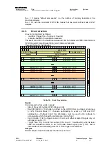
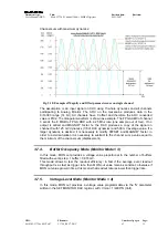
Fig. 3.19: A24 addressing
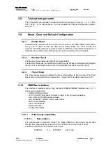
0x00000000
ÅÆ
0xFFFF0000
A32 mode
OFFSET
31
16 15
0
23
24
2
7
3
5
6
4
1
0
A
B
C
D
E
F
8 9
2
7
3
5
6
4
1
0
A
B
C
D
E
F
8 9
2
7
3
5
6
4
1
0
A
B
C
D
E
F
8 9
2
7
3
5
6
4
1
0
A
B
C
D
E
F
8 9
SW5
SW4
SW3
SW2
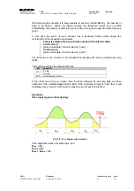
Fig. 3.20: A32 addressing
The Base Address of the module is selected through four rotary switches (see § 2.6),
then it is validated only with either a Power ON cycle or a System Reset (see § 3.8).
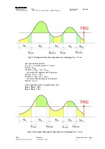
3.10.1.2. CR/CSR
address
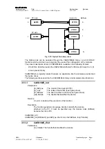
GEO address is picked up from relevant backplane lines and written onto bit 23..19 of
CR/CSR space, indicating the slot number in the crate; the recognised Address Modifier
for this cycle is 2F.
This feature is implemented only on versions with 160pin connectors
.
OFFSET
31
16 15
0
23
24
GEO
19 18
Fig. 3.21: CR/CSR addressing
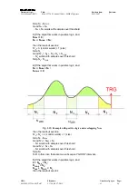
3.10.1.3. Address
relocation
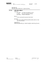
Relocation Address register (see § 4.39) allows to set via software the board Base
Address (valid values
≠
0). Such register allows to overwrite the rotary switches settings;
its setting is enabled via VME Control Register (see § 4.30). The used addresses are:
OFFSET
31
16 15
0
23
24
ADER H ADER L
software
relocation
OFFSET
31
16 15
0
23
24
ADER L
A32
A24
software
relocation
Fig. 3.22: Software relocation of base address