


Document type:
Title:
Revision date:
Revision:
User's Manual (MUT)
Mod. V1724 8 Channel 14bit - 100MS/s Digitizer
06/11/2007
7
NPO:
Filename:
Number of pages:
Page:
00103/05:V1724x.MUTx/07 V1724_REV7.DOC
63
30
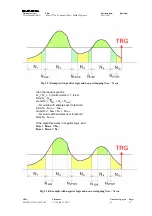
N'
2
+ N'
4
+ 4 (control words) + 1 (size)
Skip N
1
- N
LBK
Good N'
2
= N
LBK
+ N
2
+ N
LFWD
... N'
2
words with samples over threshold
Good N'
4
= (N
3
- N
LFWD
) + N
4
+ N
LFWD
... N'
4
words with samples over threshold
Skip N
5
- N
LFWD
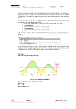
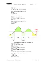
N.B: In this case there are two subsequent “GOOD” intervals.
These examples are reported with positive logic; the compression algorithm is the same
also working in negative logic.
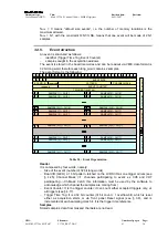
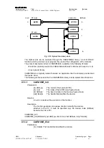
3.5. Trigger
management
All the channels in a board share the same trigger: this means that all the channels store
an event at the same time and in the same way (same number of samples and same
position with respect to the trigger); several trigger sources are available.
VME
Interface
TRG IN
Enable Mask
x8
8
8
TRIGGER
SW TRG
TRG OUT
LOCAL TRG
D
Q
SCLK
Acquisition
Logic
Memory
Buffers
ADC
Digital
Thresholds
8
Local Bus
Interface
Mother Board
Mezzanines
Fig. 3.13: Block diagram of Trigger management
3.5.1. External
trigger
External trigger can be NIM/TTL signal on LEMO front panel connector, 50 Ohm
impedance. The external trigger is synchronised with the internal clock (see § 3.2.11); if
External trigger is not synchronised with the internal clock, a one clock period jitter
occurs.
3.5.2. Software
trigger
Software trigger are generated via VME bus (write access in the relevant register, see
§ 4.20).