Unpacking and Installing Your SmartSTACK Ethernet ELS10-27
2-13
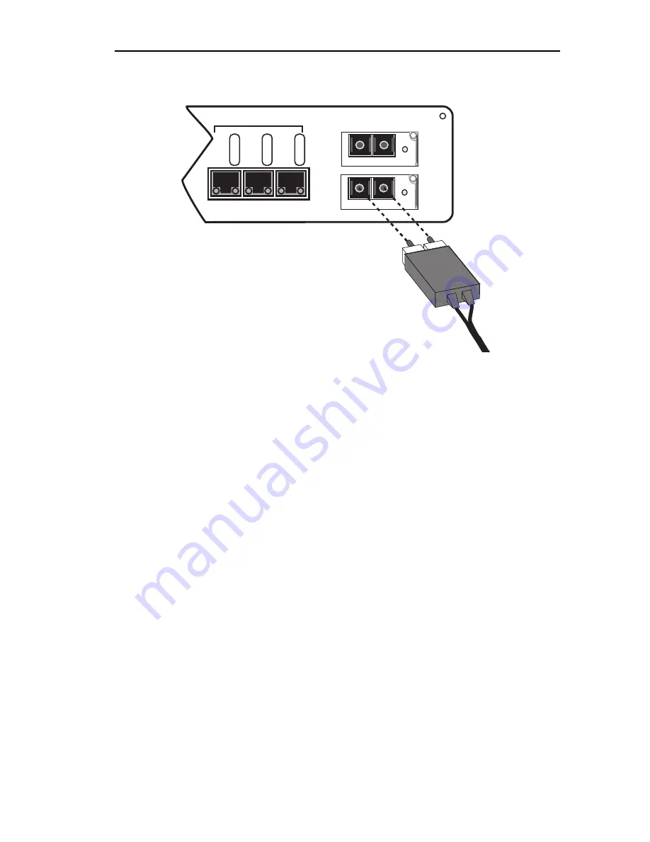
Figure 2-7. EPIM100-FX Port
4. Verify that a Link exists by checking that the port
LINK
LED is solid
green. If the
LINK
LED is off, perform the following steps until it is
on:
a. Check that the power is turned on for the device at the other end
of the Link.
b. Verify proper crossing over of fiber strands between the
applicable port on the SmartSTACK Ethernet ELS10-27 and the
fiber optic device at the other end of the fiber optic link segment.
c. Verify that the fiber connection meets the dB loss specifications.
If a Link has not been established, contact Cabletron Systems. Refer to
Section 1.2,
Getting Help
, for details.
The SmartSTACK Ethernet ELS10-27 is now ready to be set up through
Local Management. Refer to Chapter 4,
Monitoring and Managing Your
SmartSTACK Ethernet ELS10-27
, to conÞgure the SmartSTACK Ethernet
ELS10-27.
EPIM-100FX
LNK
EPIM-100FX
LNK
25X 26X 27X
10BASE-T/100BASE-TX
LINK
ST
A
TUS
LINK
ST
A
TUS
LINK
ST
A
TUS
EPIM100
EPIM100
Summary of Contents for SmartSTACK ETHERNET ELS10-27
Page 2: ......
Page 12: ...Notice x...
Page 16: ...xiv Contents...
Page 74: ...2 14 Unpacking and Installing Your SmartSTACK Ethernet ELS10 27...
Page 94: ...3 20 Configuring Your SmartSTACK Ethernet ELS10 27...
Page 108: ...4 14 Monitoring and Managing Your SmartSTACK Ethernet ELS10 27...
Page 122: ...A 8 EPIM 100FX...
Page 126: ...Index I 4...


