30
A 8
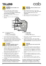
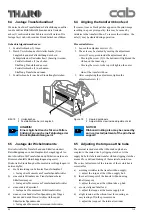
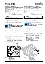
11. Remove the screws (20) from the bearing plate (19)
12. Carefully remove the bearing plate (19) from the
rollers.
13. Replace the defective roller and reassemble in reverse
order.
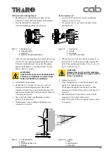
CAUTION!
The small pulley (5, fig. 7) must be
installed with lip toward the mounting
plate! Slide the bearing (18) onto the new
print roller (16)!
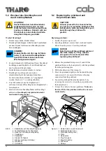
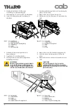
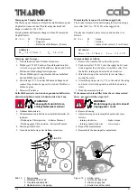
8. Druckkopf mit Hebel (12) öffnen und
Versteifung (13) nach unten klappen.
9. Sicherungsring (15) von der Achse (14) abnehmen.
10. Achse (14) herausziehen und Versteifung (13)
abnehmen.
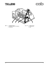
Bild 8
10 Abreißkante
11 Rändelschraube
12 Hebel Druckkopfverriegelung
13 Versteifung
14 Achse
15 Sicherungsring
Figure 8
10
Tear plate
11
Thumbscrew
12
Printhead locking lever
13
Plate
14
Axle
15
E-ring
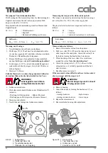
11. Schrauben (20) aus dem Lagerblech (19)
herausschrauben.
12. Lagerblech (19) vorsichtig abziehen.
13. Jeweilige Walze erneuern und in umgekehrter
Reihenfolge montieren.
ACHTUNG!
Bund am kleinen Riemenrad (5, Bild 7)
muss bei Montage zur Montagewand
zeigen! Lager (18) der Druckwalze (16)
auf die neue Druckwalze aufschieben!
Bild 9
16 Druckwalze
17 Umlenkwalze
18 Lager
19 Lagerblech
20 Senkschrauben für Lagerblech
Figure 9
16
Print roller
17
Rewind assist roller
18
Bearing
19
Bearing plate
20
Flush screws for bearing plate
13
12
14
15
11
10
16
17
19
20
18
8. Open the printhead using the lever (12) and swing the
plate (13) downwards.
9. Remove the E-ring (15) from the axle (14).
10. Pull the axle (14) out of the plate (13) and remove the
plate.

