


PANEL PRO
6
8.
Level the machine
by placing your most accurate level on the X1 bearing rail (the
bearing rail near the deep end of the pan). Adjust the leg glides for an exact level.
Repeat on the X2 bearing rail. Note that common levels are not sensitive enough.
9.
10.
Install the “X1” motor (the motor nearest to the deep side of the drain pan) using 4
6mm screws located in the box with the motors. The x axis is the one with the
longest lead screw. Tighten coupler to lead screw with a 7/64 Allen wrench (not
included).
Make sure there is no slippage between the coupler and lead screw.
11. Install the “Y” motor in a similar fashion.
Attach the Y motor to the connector
closest to the motor. Tighten coupler to
lead screw.
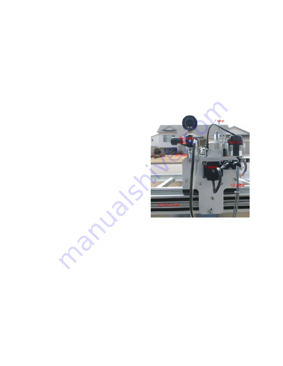
12. Attach shop air to the Y axis air fitting.
(Milton industrial) Adjusting the z axis up
and down speed is best done after the
AvCAM software is installed. Adjust the
air pressure with the knob just under and
to the side of the pressure gage to 40 psi.
Note that there is a “float” switch on the z
axis pneumatic solenoid. When the
toggle switch points away from the
operator, the pressure is released and the
z axis floats down. This is used to check
end mill position, but normal operations
should be conducted with the toggle switch in the normal automatic position toward
the operator. If the x or y axis moves with the end mill dragging on the surface there
is a high likely hood that the bit will break.
13. Unpack the coolant tank box strapped between mount bars. The drain fitting and
filter housing are located in the coolant tank for shipping. The pump is fastened to
the side of the shipping crate.
14. Install the drain fitting through the hole in the drain pan. The rubber gasket goes on
the outside with the paper washer between the rubber gasket and nut.
15. Route the 7 foot clear coolant hose from the back side of the Y assembly cable
guide to the barb fitting on the pump. The hose may be shortened as required, but it
needs to be long enough to reach when the X axis is at full travel.


