


PANEL PRO
24
When EasyCAD opens a new file, the current layer is “standard”. It is useful to
organize information on layers that can be turned on or off so as not to clutter other
information. Many of the drawings included in the drawing package have their roots
back in the “DOS” days when layers were numbered and not named. Back then we
adopted layer 2 as the layer to contain the final desired cutout sized entities and have
not changed it.
We will start by drawing the cutout. Select the layer icon
(right side, icon with 4
horizontal solid lines). Click new and type in “2” for the new layer name. Click new
again and repeat with “1”. On the lines with the layer names there are 3 boxes. The
first box if checked indicates the current layer on which any new entities will reside.
Next to that is a box that if checked indicates that layer is hidden.
For now check the layer 2 box to select it as current, and click ok.
Next move the mouse pointer to the color bar and select the third color from the bottom
“red”.
Click draw>circles>diameter and center. There are a number of methods to define the
entities. In this case we will enter the diameter of the circle and its center coordinates.
Note the data entry / command bar on the lower left of the screen. It should say
diameter (2.000) or some other number. The number displayed is the diameter that will
be drawn when you right click or hit enter unless otherwise specified. In this case type
the number 3.140 and hit enter. A 3.140 diameter circle will attach to the mouse pointer.
We want a precise center coordinate, so type the number 0,0 and hit enter or right click
on the mouse.
Now let’s draw circles to indicate the location of the mount holes. We can calculate the
coordinates with a calculator and enter each circle, but let’s use the power of CAD to do
some of the calculations.
Construction lines are temporary lines we draw to measure from.
Click the line icon (upper left side) or draw > line. Enter 0,-2 to start a line on the
centerline starting at the bottom. Click the ortho button on the bottom. This forces lines
exactly left/right or up/down. Next move the mouse so that the line extends beyond the
top of the instrument. Left click to set the end of the line.
Repeat with a line from left center (-2,0) to right center.
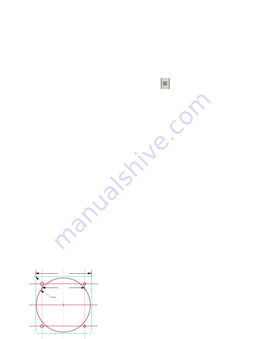
Note that the horizontal distance between mount hole
centers is 2.474. Divide this by 2 to get 1.237. Select
the offset one icon (left side 2 vertical lines) When we
draw a line, a number in parenthesis appear in the lower
Ø3.140
2.474
3.250
R0.100


