


186CNV / 284ANV: Service Manual
Manufacturer reserves the right to change, at any time, specifications and designs without notice and without obligations.
11
TROUBLESHOOTING
TROUBLESHOOTING CONTROL FEATURES
Diagnostics Display
Any active diagnostics will be continuously displayed on the matrix
display. Please refer to PCM Indicators and Display Operation in the
Control Features and Operation section for further information.
Multi-Function Forced Defrost Input (J3)
The forced defrost pins are located near the right edge of the PCM
slightly above center, between two connectors. The Forced Defrost
input has the following functions:
• Forcing Defrost
• Overriding the Compressor Protect Delay
• Activating the Diagnostic Code Recall Function
These multiple functions are available at the PCM header only. The
Forced Defrost function on the Evolution Control provides only the
Defrost Forcing function. Each of these functions is described below.
Forced Defrost
A Forced Defrost event will begin when the Forced Defrost header pins
are shorted for 5 seconds while the following conditions apply:
• The equipment is operating in Heating Mode (compressor is running)
• A defrost cycle is not already in progress
The defrost event will begin with a change in compressor speed followed
by actuation of the reversing valve. For more information on the Defrost
Process, refer to Defrost Mode under Control Features and Operation
section.
Compressor Protect Delay Override
The Compressor Protect Delay will be overridden allowing immediate
equipment start when the Forced Defrost header pins are shorted for 1
second while the equipment is not operating (compressor is off).
The override condition will be confirmed with the word OVERRIDE
scrolled across the matrix display until the compressor starts. Note that
the compressor will not attempt to start unless a demand is present, and
until pressure equalization is complete (if necessary) and the fan has
successfully started.
Diagnostic Code Recall
The Diagnostic Code Recall mode will be enabled if the Forced Defrost
pins are shorted when power is applied to the equipment. It is not
possible to enter Diagnostic Code Recall mode while power is applied to
the equipment. The recommended procedure is to remove power from
the equipment, apply a clip wire between the Forced Defrost header pins
and then apply power to the equipment.
While in Diagnostic Code Recall mode, the Display Matrix will scroll
the word RECALL followed by the most recent, highest priority
diagnostic code if that code occurred with the last 240 hours of
equipment operation. The display will repeat continuously while recall
mode is active. No code will be displayed if the most recent, highest
priority diagnostic code occurred more than 240 hours of equipment
operating time before entering recall mode. No code will be displayed if
there have never been any diagnostic codes active. If there is no code to
display, then only the word RECALL will be scrolled across the display
while the mode is active.
The equipment will not operate while the Diagnostic Code Recall mode
is active.
The equipment will exit Diagnostic Code Recall mode when the short is
removed from the Forced Defrost header pins, or 15 minutes after power
is applied to the equipment if the short is still present. Upon exiting
recall mode, the recall code display will stop, any active codes will begin
to be displayed, and the equipment will resume normal operation.
SYSTEM DIAGNOSTICS
24VAC Power Distribution
IMPORTANT:
The 24VAC power (Rc) in the PCM comes from the
transformer in the equipment. The phase of this transformer connection
is not controlled relative to the phase of the power provided by the
transformer in the indoor equipment (Rh). Wiring requirements in this
manual do not connect Rc and Rh together. For any non-standard
wiring, care should be taken to make sure that Rc and Rh are not
connected together. Doing so may result in destroying one or both of the
transformers in this and the internal equipment.
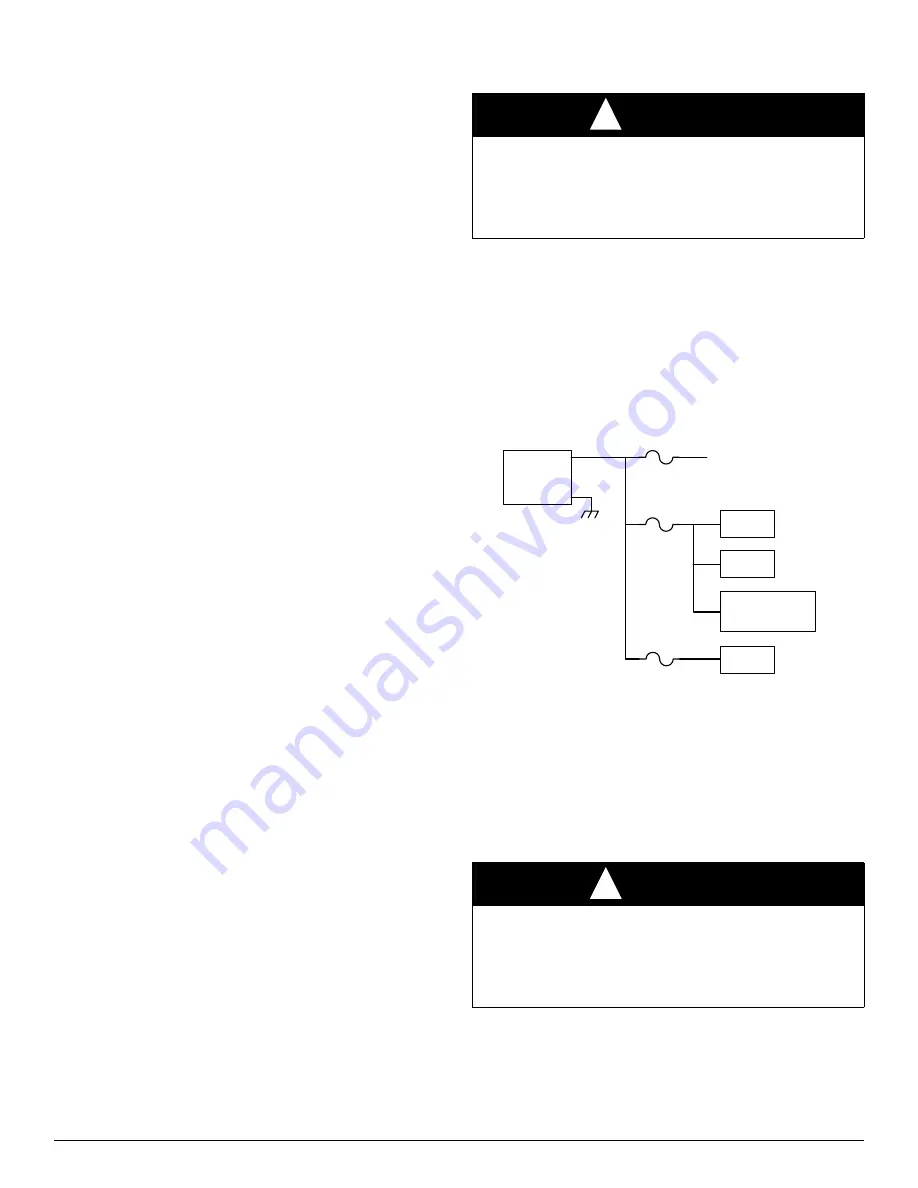
The transformer in the equipment provides power to the PCM and
numerous control components in the equipment. The power distribution
and fuse connections for this power distribution are shown in
A200252
Fig. 10 – 24VAC Power Distribution Diagram
Communication
If communication with the Evolution Control is lost, this will be
indicated by the Comm light being off. There is no diagnostic fault
associated with this condition. When communication with the Evolution
Control is lost, the equipment will default to the discrete control inputs
for operation. Refer to Control Connection in the Control Sub-System
section for further information.
Equipment Configuration (Model Plug)
Each control board contains a model plug. The model plug is used to
identify the type and size of equipment to the control. The correct model
plug must be installed for the system to operate properly (see
).
Refer to Equipment Configuration in the Control Features and Operation
section for further information.
CAUTION
!
EQUIPMENT DAMAGE HAZARD
Failure to follow this caution may result in equipment damage or
improper operation.
Do not connect the equipment 24VAC supply (Rc) to the indoor
equipment 24VAC supply (Rh).
CAUTION
!
EQUIPMENT DAMAGE HAZARD
Failure to follow this caution may result in equipment damage or
improper operation.
Do not attempt to operate system with incorrect model plug as this
could cause equipment damage.
TRANS
FORMER
PEV
Bluetooth
£
Module
FUSE1
FUSE2
MAIN PCM POWER
MAIN
FUSE
RVS
LLS
R
C


