background image

Bandit

Copyright 1/10 

PAGE 9

MODELS 65XP(XL)/95 


MAINTENANCE SECTION

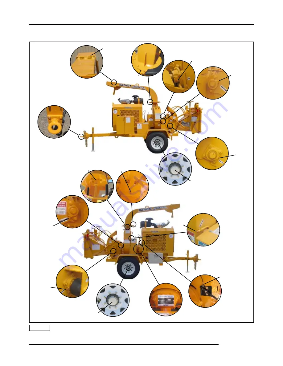
LUBRICATION CHART

NOTICE  Use as a reference only, locations may vary depending on options or component manufacturer.   


Lubrication point instructions are described on the machine, in the Lubrication & Coolant Section  


and Maintenance Section of this manual, or component manufacturer’s manual.

11

9

7

8

10

11

1

1

Summary of Contents for 65XL

Page 1: ...TRIES INC 6750 Millbrook Road REMUS MICHIGAN USA 49340 PHONE 800 952 0178 IN USA PHONE 989 561 2270 OR 561 2272 FAX 989 561 2273 SALES DEPT FAX 989 561 2962 PARTS SERVICE E MAIL www banditchippers com...

Page 2: ...ONENTS 94 CHIPPER KNIFE HARDWARE 98 ANVIL HARDWARE 99 DISCHARGE COMPONENTS 100 HYDRAULIC COMPONENTS 107 FRAME ACCESSORY COMPONENTS 120 FUEL HYDRAULIC TANK COMPONENTS 126 CHIP BOX ACCESSORY COMPONENTS...

Page 3: ...e and follow a regularly scheduled preventative maintenance and repair program on the product using only factory approved replacement parts Any unapproved repairs or modifications may not only damage...

Page 4: ...r installing bolt on or slip on items such as hydraulic pumps and motors control valves flow dividers belts sheaves etc The manufacturer will provide replacement parts to the customer for defective pa...

Page 5: ...consequential or incidental loss shall be available to him or her It is absolutely necessary to return the Warranty Validation Form completely and accurately filled out and notify Bandit Industries I...

Page 6: ...other components are warranted by their respective manufacturers i e engines axles hydraulic pumps and motors clutches tires batteries etc Any machines used for lease or rental purposes warranty is l...

Page 7: ...ONS 1 Beltshield 2 Hinged chipper hood under handle 95 only 3 Top of throat 4 Tongue and a frame side 5 Top of frame 6 W O on top of tongue SERIAL NUMBER LOCATIONS The engine information is located on...

Page 8: ...gs or alcohol Keep children bystanders and animals clear of working area Never operate equipment that is in need of repair or adjustment Before starting the machine take a minute to check a few things...

Page 9: ...t the larger diameter wood When feeding larger diameter wood listen for the engine to possibly lug down If it starts lugging down stop the feedwheel s by pushing the hydraulic control bar to off and l...

Page 10: ...like material into 4 to 5 foot 1 2 to 1 5 meter length s away from the chipper area DO stop the feed system before feeding the cut vine like material into the infeed hopper DO use a wooden pusher pad...

Page 11: ...tch PTO is a very expensive item that will fail if not correctly maintained and adjusted It will be quite costly if a few minutes are not taken daily weekly and monthly to keep the clutch serviced as...

Page 12: ...e time watching the material being fed Once the limbs have started into the machine you can walk away and get more material Keep the feedwheel tension springs adjusted only tight enough to keep the fe...

Page 13: ...R DO NOT entangle feet or hands in undercarriage travel system DANGER NEVER sit stand lay climb or ride anywhere on this machine while it is running operating or in transit You will be injured DANGER...

Page 14: ...75 to 3357 kg Not Shown Approximate weights depending on engine and equipment options Overall Model 65 Height 7 6 2 3m Length 12 10 3 9m Width 5 7 1 7m Dimension Model 65 Chip Box Height 8 8 2 6m Leng...

Page 15: ...2600 lbs 1179 kg Approximate weights depending on engine and equipment options Overall Model 65 PTO 3 POINT Height 7 6 2 3m Length 8 7 2 6m Width 4 6 1 4m Dimension Model 65 PTO TRAILERIZED Height 7 7...

Page 16: ...Bandit Copyright 1 10 PAGE 15 MODELS 65XP XL 95 DECALS DECALS...

Page 17: ...S 65XP XL 95 DECALS DECAL LOCATIONS MODEL 65 Decal locations may vary these are general locations 19 22 29 31 32 34 3 36 4 9 2 16 17 20 28 38 41 42 7 26 2 15 18 12 23 37 2 17 20 30 5 6 10 11 25 33 39...

Page 18: ...nd Lay Climb 11 SPD 34 Brush Chippers Are Very Dangerous 12 ID 42 Bandit Industries Inc USA 13 INST 02 Yoke Lock Hole 14 INST 03 Yoke Lock Bar 15 INST 04 Arrow 16 INST 11 Motor Coupler Guard 17 INST 1...

Page 19: ...S 65XP XL 95 DECALS DECAL LOCATIONS MODEL 65 Decal locations may vary these are general locations 19 22 29 31 32 34 3 36 4 9 2 16 17 20 28 38 41 42 7 26 2 15 18 12 23 37 2 17 20 30 5 6 10 11 25 33 39...

Page 20: ...00 30 Basic Safety Decal Kit Options may require additional decals 44 900 8900 12 Bandit Model 65 Logo Decal Kit Additional Decals for Machine Equipped With A Chip Box Consult dealer or manufacturer f...

Page 21: ...CALS DECAL LOCATIONS MODEL 95 Decal locations may vary these are general locations 7 11 46 14 1 6 12 4 17 8 34 52 16 32 31 33 47 48 49 10 23 2 15 23 38 50 29 30 37 39 41 42 44 2 22 23 5 35 36 25 27 28...

Page 22: ...USA 15 INST 02 Yoke Lock Hole 16 INST 03 Yoke Lock Bar 17 INST 04 Arrow 18 INST 05 Yoke Lift Up Down 19 INST 07 Discharge Swivel Right Left 20 INST 08 Winch Control Out In 21 INST 09 Selector Winch F...

Page 23: ...CALS DECAL LOCATIONS MODEL 95 Decal locations may vary these are general locations 7 11 46 14 1 6 12 4 17 8 34 52 16 32 31 33 47 48 49 10 23 2 15 23 38 50 29 30 37 39 41 42 44 2 22 23 5 35 36 25 27 28...

Page 24: ...ions may require additional decals 54 900 8900 14 Bandit Model 95 Logo Decal Kit Additional Decals for Machine Equipped With A Chip Box Consult dealer or manufacturer for general locations 55 SPD 47 I...

Page 25: ...t with a decal attached be sure and replace the decal 4 Replacement decals are available and can be purchased from the manufacturer or your Bandit Dealer 5 Combination English Spanish decals are typic...

Page 26: ...Bandit Copyright 1 10 PAGE 25 MODELS 65XP XL 95 DECALS...

Page 27: ...Bandit Copyright 1 10 PAGE 26 MODELS 65XP XL 95 DECALS...

Page 28: ...speed switch The switch can be adjusted so that at a given RPM an electronic relay system will operate the hydraulic solenoid valves to stop the feedwheels until the engine has recovered speed The pa...

Page 29: ...achines it will have a connector with a light screwed to it When the solenoid is activated indicated by the light in the connector the feedwheel s are reversed by the autofeed plus system See Figure 3...

Page 30: ...and or cartridge Check fuse on dump valve signal wire if equipped Checkcontinuityonthedumpvalvewire normallygreenwire Check autofeed tachometer settings Check autofeed tachometer settings Check for s...

Page 31: ...50 3450 2650 2450 2650 3300 2650 2250 2650 2650 2650 2850 On RPM 2650 2650 2400 2400 2150 2150 2150 2400 2150 2400 2400 2650 2600 3100 2400 2200 2250 2650 2400 2050 2400 2400 2400 2650 Magnetic Pick U...

Page 32: ...HE 1 JAM NUT TO ADJUST CONTROL HANDLE PIVOT TENSION PUSH TO REVERSE FEEDING ADJUST PIVOT TENSION WITH THE TIGHTNESS OF INSIDE FRICTION NUTS SECURE ADJUSTMENT WITH OUTSIDE JAM NUTS ADJUSTING TENSION FO...

Page 33: ...95 Option 4 Lug Nuts Yoke Lift Cylinders 95 Option 5 Feedwheel Motor Coupler Adjustable Height Discharge Optional 6 Infeed Hopper 7 Folding Infeed Pan 8 Feedwheel Control Bar 9 Hydraulic Control Valve...

Page 34: ...95 Option 4 Engine Controls Adjusters Discharge Flipper Adjuster 65 5 Electric Engine Throttle Adjuster if equipped Infeed Hopper 6 Bandit Lever Throttle Adjuster if equipped 7 Clutch Handle if equip...

Page 35: ...ctric switch push the switch out towards the material to make the winch reel out and push the switch away from the material to make the winch pull material in Discharge Swivel Control Optional NOTE Re...

Page 36: ...to the material to be reeled in Attach cable securely to wood material that you want pulled to chipper 5 Make sure everyone is clear and then retract the clutch lock pin and then pull the clutch hand...

Page 37: ...the chipper engine disable plug is not properly installed then the engine will not start or run If the chipper engine disable plug becomes disconnected while the chipper engine is running the engine w...

Page 38: ...led in place holding the chipper hood in the closed position see figure 1 With the chipper hood shut and hood pin in place the spring lock helps keep the hood pin from sliding out or from being remove...

Page 39: ...engines may have a choke adjustment pull the choke lever out to choke the engine Push the choke lever in for normal engine operations 5 Throttle Adjustment if equipped Some engines may have a knob or...

Page 40: ...transporting the machine Also check brakes if equipped to make sure they are operating correctly 14 Do not transport unless discharge is clamped pinned and bolted securely into place in the transport...

Page 41: ...DING OR UNLOADING THE MACHINE INSPECT AND CONFIRM THE FOLLOWING STEPS When loading or unloading the self propelled machine on the trailer use care and caution The maneuvering of the equipment must be...

Page 42: ...e engine ECM engine control module before welding Follow the specific Engine MFG instructions for proper welding and grounding procedures before attempting to weld on the machine If welding on the mac...

Page 43: ...maintenance or neglect will cause overheating problems and engine failure 7 Check chipper disc assembly Check for elongated bolt holes secure welds torqued bolts excessive wear and impact cracks If a...

Page 44: ...Check tires Check tires for wear weather checking and damage Replace if damaged 26 Inspect axle dust caps Inspect axle dust caps and replace if damaged or leaking 27 Inspect adjust and lubricate track...

Page 45: ...sharpness Replace if needed 5 Check chipper bearings and chipper sheave Check retighten all bearing bolts bearing lock collars and also belt sheave bushings to correct torques 6 Check hydraulic functi...

Page 46: ...s 95 and 65 Belt Side 5 8 11 NC 150 203 Chipper Bearing Bolts 65 Infeed Hopper Side 1 2 13 NC 70 95 Chipper Shaft Bearing Retainer 95 3 4 10 NC 170 230 Chipper Shaft Bearing Retainer 65 5 8 11 NC 150...

Page 47: ...gs purge and feedwheel bearings 1 shot daily 13 Grease yoke pivot bearings with 1 shot 14 Check and or adjust belt tension on chipper and hydraulic pump belt drives 15 Check hydraulic pump and motor s...

Page 48: ...e oil filter s if equipped after first 10 hours then quarterly or every 400 hours WHEN YOU CHANGE CHIPPER KNIVES CHECK CHIPPER DISC ASSEMBLY FOR ELONGATED KNIFE BOLT HOLES SECURE WELDS TORQUED BOLTS E...

Page 49: ...4 Hood Hinge X 1 to 2 shots of grease wipe off excess 5 Steel Friction Areas pivoting X Lubricate i e control handle discharge hinged sliding rolling flipper folding pan winch rollers etc 6 Chain Driv...

Page 50: ...Use as a reference only locations may vary depending on options or component manufacturer Lubrication point instructions are described on the machine in the Lubrication Coolant Section and Maintenanc...

Page 51: ...t instructions are described on the machine in the Lubrication Coolant Section and Maintenance Section of this manual or component manufacturer s manual CHECK DESCRIPTION DAY WEEK MONTH PROCEDURE 1 St...

Page 52: ...HART CHIP BOX NOTICE Use as a reference only locations may vary depending on options or component manufacturer Lubrication point instructions are described on the machine in the Lubrication Coolant Se...

Page 53: ...lts see Torque Chart for the correct torque on the opposite side of the engine from the engine adjusters 6 Loosen the jam nuts on the engine adjuster on the radiator end of the engine 7 Torque the eng...

Page 54: ...with 12 to 13 lbs of force for a Model 65 if equipped with a Honda engine 9 to 10 lbs of force Main Drive belts maximum of 3 8 deflection with 10 to 12 lbs of force for a Model 95 Pump Drive belts max...

Page 55: ...raulic pump the hose can be capped with a 10 male JIC cap 6 Remove the bolts that hold the torque arm to the hydraulic pump 7 Remove the old drive belts and place the new drive belts on The engine may...

Page 56: ...ock out the pin You may have to run impact on bolt and hit with hammer a few times to remove pin Do not spend excessive time trying to remove the pin and coupler If problems occur during pin and coupl...

Page 57: ...the infeed hopper or under the top feedwheel remove the yoke springs from the top yoke raise the yoke install the yoke lock pin safety chain the yoke in the raised position and insert a wooden block t...

Page 58: ...njured Do Not Do This DANGER Anvil Adjustment Procedure 1 To adjust the anvil first loosen two of the hex nuts on either the inside or outside of the anvil puller block If the anvil needs to be adjust...

Page 59: ...is use a degreaser 2 Install both feedwheel bearings on the feedwheel shaft with the Grip Tight bearing on the hydraulic motor side and the set screw bearing on the opposite side Do not lock the beari...

Page 60: ...te Then two people must remove the chute Do not attempt this with one person because the chute can fall causing injury If used properly a hoist can be used to assist in the removal of the chute 5 Neve...

Page 61: ...ly Simply sand the edges of the damaged paint area mask off the surrounding area and apply primer and paint to the dry clean and warm surface This will help keep the damaged area from spreading or get...

Page 62: ...ce all brakes of this type must be burnished or run in before their full effectiveness can be achieved the MFG maintenance manuals call for readjustment after the first 200 miles 322 km of operation T...

Page 63: ...WARNING This machine is equipped with Petro Canada Hydrex XV hydraulic fluid It is recommended to replace with the same Petro Canada Hydrex XV is an all season hydraulic fluid This is a premium perfor...

Page 64: ...ng operation The actual viscosity needed is based on oil temperature during operation and not air temperature Compare your fluid specifications with the specifications below to verify compliance When...

Page 65: ...3 0 11 4 3 0 11 4 N A 27 28 1800 124 1800 124 N A 65 PTO 3 Knife 540 RPM 4 3 16 3 4 3 16 3 N A 40 41 1800 124 1800 124 N A 65 2 Knife Dual Feedwheels 5 5 20 8 2 75 10 4 2 75 10 4 30 31 1800 124 1800 1...

Page 66: ...2500 172 2200 152 500 800 34 55 500 800 34 55 2200 152 95 PTO 2 Knife 540 RPM 3 5 13 2 3 5 13 2 23 24 2000 138 2000 138 800 55 N A 2200 152 500 800 34 55 500 800 34 55 N A 95 PTO 2 Knife 1000 RPM 3 5...

Page 67: ...ecified PSI bar This will cause damage to hydraulic components Do not set any other hydraulic component past it s specified pressure or this will cause damage to the hydraulic components Keep hydrauli...

Page 68: ...ything which has been disassembled or tampered with will not be warranted Items being returned must be clean All hydraulic components must have all hosing ports plugged Failure to plug ports will allo...

Page 69: ...which weakens the feedwheel power The relief as well as hydraulic oil and screen must be kept clean 1 VALVE SEAT The springs pushes the relief valve ball against it until pressure builds 2 POPPIT VAL...

Page 70: ...t the control handle in the off position 2 Disconnect the hydraulic hose going from the control valve to the feedwheel motor at the feedwheel control valve end 3 Leave all other hydraulic hoses connec...

Page 71: ...e off position 2 Disconnect the hydraulic hose going from the control valve to the feedwheel motor at the feedwheel control valve end 3 Leave all other hydraulic hoses connected 4 Install pressure gau...

Page 72: ...essure gauge MUST be installed correctly 1 First put the control handle in the off position 2 Disconnect hydraulic hose going from autofeed plus block to feedwheel control valve at the feedwheel contr...

Page 73: ...ed 5 Start engine with the control handle in the off position 6 Adjust engine to full throttle 7 Only operate the valve for that component to activate pressure gauge Pressure gauge should read the max...

Page 74: ...2 Clean reset or replace feeding 3 Pump is worn 3 Replace 4 Motor is worn 4 Replace 5 Feedwheel springs too tight 5 Adjust 6 Feedwheel slide box sticking or 6 Lubricate hanging up Feedwheel s turn 1...

Page 75: ...lic pressure adjustment procedure section of the valve setting manual to find the correct procedure for adjusting relief valve pressure settings pgs 68 72 Cleaning relief valve 1 Remove plug from feed...

Page 76: ...o the control valve at the valve some machines will be equipped with a flow divider between the hydraulic motor and the control valve If the hydraulic motor has a case drain unhook the case drain hose...

Page 77: ...e pump the clutch may have to be engaged if the pump is belt driven 8 Have a second person lift the hydraulic hose far enough out of the tank inlet to observe the flow of oil going into the tank Obser...

Page 78: ...gauge reading to make sure a high pressure does not exist 8 Increase the engine speed slowly to full rpm and at the same time observe the pressure and flow rate The pressure should still remain low M...

Page 79: ...debris and shop rags 3 16 Tee handle hex driver 1 2 drag link drive socket Jawed vice General Procedure Disassembly 1 Secure valve in vice or suitable method to firmly hold valve 2 Note the orientati...

Page 80: ...0 PAGE 79 MODELS 65XP XL 95 SPECIFIC SCHEMATIC FUNCTION MAY VARY DEPENDING ON OPTIONS OR COMPONENT MANUFACTURE WITH NO OPTIONS HYDRAULIC SECTION MODELS 65 95 FEEDWHEEL MOTOR CONTROL VALVE PUMP SUCTION...

Page 81: ...L 95 SPECIFIC SCHEMATIC FUNCTION MAY VARY DEPENDING ON OPTIONS OR COMPONENT MANUFACTURE WITH NO OPTIONS HYDRAULIC SECTION MODEL 65 WITH DUAL FEEDWHEELS FEEDWHEEL MOTOR FEEDWHEEL MOTOR FLOW DIVIDER CON...

Page 82: ...RY DEPENDING ON OPTIONS OR COMPONENT MANUFACTURE WITH AUTOFEED PLUS YOKE LIFT CYLINDER WINCH HYDRAULIC SECTION FEEDWHEEL MOTOR CONTROL VALVE PUMP SUCTION SCREEN TANK FILTER CONTROL VALVE CONTROL VALVE...

Page 83: ...engine on large material keep engine RPM up B Knives are dull or worn to minimum size C Obstruction in discharge chute Patches welded into the chute can cause obstruction of chip flow Anything causing...

Page 84: ...olt In Knives Starting 2 96 35 Angle Knives should be replaced in sets These sets are determined by the amount of resharpening done to the knives knife width Regrinding knives reduces the width of the...

Page 85: ...e welds excessive wear impact cracks and elongated bolt holes on disc chippers or the condition of the knife bolt threads on drum chippers If a problem is found contact your local dealer or Bandit Ind...

Page 86: ...es of bearings are designed with a relief system that will not allow over greasing In other words you can not hurt the bearing seals by pumping in too much grease Wipe off excess grease Excessive grea...

Page 87: ...Ground Green G Right Turn Yellow Y Left Turn Brown BR Running Lights Red R Breakaway Switch WIRING FOR STANDARD 6 PRONG PLUG AND 6 WIRE MAIN CABLE EFFECTIVE ON MACHINES BUILT AFTER 11 01 04 6 WIRE MAI...

Page 88: ...erves the right to make changes in models size design installations and applications on any part without notification All nuts bolts washers and many other components can be ordered by physical descri...

Page 89: ...Bandit Copyright 1 10 PAGE 88 MODELS 65XP XL 95 INFEED HOPPER COMPONENTS 42 NOTICE Parts may not be exactly as shown...

Page 90: ...Light 17 a 980 0122 55 980 0122 55 Wooden Push Paddle Mount b 900 4914 18 900 4914 18 Plastic Knob Not Shown 18 626 0001 80 980 300139 Hydraulic Control Arm 19 980 100141 980 100141 Feedwheel Control...

Page 91: ...Bandit Copyright 1 10 PAGE 90 MODELS 65XP XL 95 INFEED HOPPER COMPONENTS 42 NOTICE Parts may not be exactly as shown...

Page 92: ...Guard Mount Not Shown 34 980 0124 98 981 1006 44 Feedwheel Torque Arm 35 a 900 3927 67 900 3908 68 Feedwheel Hydraulic Motor Tapered Shaft b N A 900 3908 19 Feedwheel Hydraulic Motor RE 32 Straight Sh...

Page 93: ...Bandit Copyright 1 10 PAGE 92 MODELS 65XP XL 95 DUAL FEEDWHEEL COMPONENTS MODEL 65 DUAL FEEDWHEEL NOTICE Parts may not be exactly as shown...

Page 94: ...00 04 Yoke Spring 9 900 1901 08 Yoke Pivot Bearing 10 626 200010 Top Yoke Assembly 11 937 900009 Torque Arm Cushion 12 a 980 300515 Top Torque Arm Stop b 937 300316 Torque Arm Cushion Mount 13 a 900 1...

Page 95: ...Bandit Copyright 1 10 PAGE 94 MODELS 65XP XL 95 CHIPPER COMPONENTS MODEL 65 NOTICE Parts may not be exactly as shown...

Page 96: ...Page 97 980 0123 82 Chipper Disc Lock Tube On Disc 15 a 900 4901 83 900 4908 27 Discharge Spring Lock b 900 7900 93 900 7900 96 Rubber Cap Not Shown 16 626 100030 N A Engine Disable Plug Kit Honda Rob...

Page 97: ...Bandit Copyright 1 10 PAGE 96 MODELS 65XP XL 95 CHIPPER COMPONENTS MODEL 65 NOTICE Parts may not be exactly as shown...

Page 98: ...00 3900 69 900 3900 24 Grease Line for Rear Chipper Bearing 39 a 900 1903 30 900 1900 34 Rear Chipper Bearing b 900 4901 21 900 4903 32 Rear Chipper Bearing Bolt Not Shown c 900 4906 87 900 4906 87 Lo...

Page 99: ...8 96 b 900 9900 94 9 16 x 2 3 4 x 10 1 8 Double Bevel Chipper Knife Pre 2 8 96 Not Shown 5 a 900 4900 53 1 2 13NC x 2 1 2 Chipper Knife Bolt Start 2 8 96 70 80 ft lbs or 95 108 Nm of Torque b 900 490...

Page 100: ...74 N A 1 2 13NC x 2 Hex Head Bolt b N A 900 4906 95 5 8 11NC x 2 1 2 Hex Head Bolt 8 a 900 4906 72 N A 1 2 13NC x 1 1 2 Hex Head Bolt b N A 900 4906 93 5 8 11NC x 1 3 4 Hex Head Bolt 9 a 900 4906 82...

Page 101: ...sher 8 626 300106 980 300349 Hood Flange 9 626 300401 980 300424 Bottom Swivel Ring 10 626 0501 07 980 0509 94 Optional Clean Out Door Assembly Pre 9 06 11 a 900 4910 54 N A Discharge Transport Bolt 3...

Page 102: ...0 200089 Straight Section Hand Crank Adj Height Discharge 10 626 300114 981 1001 63 Discharge Flipper Hinge 11 a 626 200037 980 0509 26 12 Discharge Flipper Assembly Includes 10 12 b 626 200038 980 05...

Page 103: ...Bandit Copyright 1 10 PAGE 102 MODELS 65XP XL 95 DISCHARGE COMPONENTS HAND CRANK SWIVEL DISCHARGE NOTICE Parts may not be exactly as shown PRIOR MODEL 65...

Page 104: ...10 626 300193 980 0127 32 Sprocket For Hand Crank Swivel Discharge Weld On 11 900 4905 00 980 0137 35 Spacer Block 12 626 300107 980 0128 23 Bottom Swivel Ring 13 a 626 200039 980 0510 23 Adjusting S...

Page 105: ...6 900 1901 21 Sprocket For Hydraulic Motor 7 980 0110 63 Sprocket For Discharge Weld On 8 980 0137 35 Spacer Block 9 980 0122 18 Bottom Swivel Ring 10 914 1006 17 Hydraulic Swivel Motor Mount 11 981 1...

Page 106: ...980 0126 48 Flipper Lug 6 980 0510 02 Hydraulic Flipper Assembly Enclosed Includes 4 5 7 900 3930 71 Cylinder Lug Pin 3 4 Dia x 2 1 2 Cotter Pin 1 4 x 1 1 2 8 900 3928 16 Hydraulic Flipper Cylinder 9...

Page 107: ...scopic Discharge Lock Handle 8 981 1001 63 Discharge Flipper Hinge 9 a 980 0509 26 12 Discharge Flipper Assembly Includes 8 10 b 980 0510 25 12 Enclosed Discharge Flipper Assembly Includes 8 10 c 980...

Page 108: ...00 3909 89 Feedwheel Control Valve With Relief Pipe Fitting 6 a 900 3927 67 900 3908 68 Feedwheel Hydraulic Motor Tapered Shaft b N A 900 3908 19 Feedwheel Hydraulic Motor RE 32 With Straight Shaft c...

Page 109: ...TYPICAL MODELS 65 95 HYDRAULIC SCHEMATIC With Options Examples of straight fittings PIPE FITTING JIC SAE O RING 18 14 25 19 17 12 20 22 21 23 7 T P 13 11 14 10 9 8 5 4 9 1 3 2 6 24 15 16 17 26 16 To Y...

Page 110: ...00 3920 58 900 3913 41 12 a N A 900 3921 57 Winch Hydraulic Motor SAE O ring b N A 900 3902 14 Winch Hydraulic Motor Pipe Fitting 13 a N A 900 3920 01 Winch Control Valve SAE O ring b N A 900 3901 42...

Page 111: ...TYPICAL MODELS 65 95 HYDRAULIC SCHEMATIC With Options Examples of straight fittings PIPE FITTING JIC SAE O RING 18 14 25 19 17 12 20 22 21 23 7 T P 13 11 14 10 9 8 5 4 9 1 3 2 6 24 15 16 17 26 16 To Y...

Page 112: ...Valve Pipe Fitting 24 N A 900 3925 94 Tongue Jack Check Valve 25 N A 900 3934 24 Tongue Jack Cylinder Welded 26 N A 900 3907 31 Relief Block Machines With Yoke Lift Without Autofeed 27 a 980 100121 98...

Page 113: ...S 65XP XL 95 HYDRAULIC COMPONENTS MODEL 65 WITH DUAL FEEDWHEEL OPTION HYDRAULIC SCHEMATIC T P 3 1 2 4 5 6 7 8 9 WITHOUT FLOW DIVIDER PRE 4 05 WITH FLOW DIVIDER START 4 05 4 5 6 7 8 9 10 T P 3 1 2 NOTI...

Page 114: ...Control Valve Without Relief Pipe Fitting 8 900 3927 67 Top Feedwheel Hydraulic Motor 9 900 3944 21 Bottom Feedwheel Hydraulic Motor 10 See Pages 116 117 Flow Divider Start 4 05 11 a 980 100121 In Li...

Page 115: ...ue Retainer Nut to a Maximum of 4 to 6 ft lbs 5 to 8 Nm and Install Vibra Tite Over Torque Will Cause Damage and Will Also Void Warranty Torque Autofeed Cartridge Nut to a Maximum of 4 to 6 ft lbs 5 t...

Page 116: ...T NUMBER DESCRIPTION 1 a N A 900 3920 20 Retainer Nut and Sealing Ring Danfoss b N A 900 3915 19 Retainer Nut Northman 2 900 2909 55 900 2909 55 Herschman Connector Only 3 a N A 900 3920 19 Solenoid O...

Page 117: ...Bandit Copyright 1 10 PAGE 116 MODELS 65XP XL 95 HYDRAULIC COMPONENTS HOSE CLAMP HOSE GUARD FLOW DIVIDER Model 65 With Dual Feedwheel Option Start 4 05 NOTICE Parts may not be exactly as shown...

Page 118: ...913 32 1 2 Double Clamp Assembly For Steel Lines Includes s 1 4 g 900 3914 03 3 4 Single Clamp Assembly Includes s 1 4 h 900 3914 07 3 4 Double Clamp Assembly Includes s 1 4 i 900 3914 04 1 Single Cla...

Page 119: ...18 MODELS 65XP XL 95 HYDRAULIC COMPONENTS 1 2 3 4 6 7 8 9 10 11 12 13 6 6 6 7 9 TYPICAL FEEDWHEEL CONTROL VALVES TYPICAL SPRING LOADED CONTROL VALVE 11 9 8 4 12 6 6 7 2 1 12 3 12 6 6 7 10 NOTICE Parts...

Page 120: ...T 8 900 3901 12 Relief Valve Kit Spring Ball Screw NOTE SOLD ONLY AS A KIT 9 904 0003 34 Valve Spool Stop For Spring Loaded Valve 10 904 0003 35 Valve Spool Spring 11 904 0003 36 Valve Spacer For Yoke...

Page 121: ...Bandit Copyright 1 10 PAGE 120 MODELS 65XP XL 95 FRAME ACCESSORY COMPONENTS NOTICE Parts may not be exactly as shown...

Page 122: ...Battery b 900 6900 02 900 6900 02 660 CCA Battery c 900 6911 62 900 6911 62 1010 CCA Battery 11 a 900 7900 01 900 7900 01 Plastic Battery Liner Box for 460 CCA Battery b 900 7900 08 900 7900 08 Plasti...

Page 123: ...Bandit Copyright 1 10 PAGE 122 MODELS 65XP XL 95 FRAME ACCESSORY COMPONENTS NOTICE Parts may not be exactly as shown...

Page 124: ...00 Lbs Rubber Castor Wheel Jack Round Mount e N A 900 5908 44 5 000 Lbs Side Crank Jack Zinc Square Mnt Replaces 900 5903 86 f N A 900 5906 11 5 000 Lbs Top Crank Jack Zinc Square Mnt Replaces 900 590...

Page 125: ...Bandit Copyright 1 10 PAGE 124 MODELS 65XP XL 95 FRAME ACCESSORY COMPONENTS NOTICE Parts may not be exactly as shown...

Page 126: ...R 14 Tire Only f 900 5901 60 N A 14 Black 5 Bolt Rim Only g N A 900 5904 20 245 75R 16 Tire and White Spoke 8 Bolt Rim h N A 900 5904 40 245 75R 16 Tire and Black 8 Bolt Rim i N A 900 5904 18 245 75R...

Page 127: ...Bandit Copyright 1 10 PAGE 126 MODELS 65XP XL 95 FUEL HYDRAULIC TANK COMPONENTS MODEL 65 TANKS COMPONENTS NOTICE Parts may not be exactly as shown...

Page 128: ...e For Tank With Locking Cap b P812 Key For Padlock Not Shown 7 a 900 2903 93 Optional Rochester Sight Gauge For 8 Gallon Fuel Tank 7 Gallon Hydraulic Tank b 900 2903 94 Optional Rochester Sight Gauge...

Page 129: ...Bandit Copyright 1 10 PAGE 128 MODELS 65XP XL 95 FUEL HYDRAULIC TANK COMPONENTS MODEL 95 TANKS COMPONENTS NOTICE Parts may not be exactly as shown...

Page 130: ...Barb c 900 3926 82 3 8 NPTF To 3 8 Hose Barb d 900 3931 53 3 8 NPTF To 5 16 Hose Barb 10 a 980 0509 58 24 1 2 Gallon Rectangle Fuel Tank Assembly b 900 3908 92 24 1 2 Gallon Rectangle Plastic Fuel Ta...

Page 131: ...Bandit Copyright 1 10 PAGE 130 MODELS 65XP XL 95 CHIP BOX ACCESSORY COMPONENTS CHIP BOX PRIOR TURNTABLE PRE 1 07 PRIOR LIGHT MOUNTS PRE 1 07 NOTICE Parts may not be exactly as shown...

Page 132: ...913 46 Turntable Bearing Start 1 07 14 900 3906 77 Chip Box Lift Cylinder 15 900 2915 98 LED Red Marker Light 16 900 2900 06 Amber Rectangle Reflector 17 a 910 200012 Curb Side Door Assembly Start 1 0...

Page 133: ...Bandit Copyright 1 10 PAGE 132 MODELS 65XP XL 95 CHIP BOX ACCESSORY COMPONENTS CHIP BOX PRIOR TURNTABLE PRE 1 07 PRIOR LIGHT MOUNTS PRE 1 07 NOTICE Parts may not be exactly as shown...

Page 134: ...902 29 Engine Adjuster Rod End 1 2 13NC x 6 b 900 4902 28 Engine Adjuster Rod End 1 2 13NC x 8 1 2 c 900 4902 73 Engine Adjuster Rod End 1 2 13NC x 5 1 2 36 900 5906 10 2 000 Lbs Yoke Lift Jack Side C...

Page 135: ...rum Not Shown 8 900 3905 17 Winch Clutch 9 40473 Winch Brake Shoe Only 10 40024 Winch Spring 11 a 40469 Winch Shift Lever Only b 900 3905 16 Winch Shift Lever With s 9 10 12 a 40025 Winch Pin For Brak...

Page 136: ...007 14 Pin For Welded Cylinder Not Shown 2 914 1000 38 Lock Pin 3 980 0131 50 Inside Tube Assembly 4 980 0509 53 Drop Leg Foot Pad Assembly 5 900 3925 94 Check Valve 6 a 900 3920 01 Tongue Jack Valve...

Page 137: ...Tab Foldaway Radiator Screen 3 Mount Tray For Foldaway Radiator Screen 4 900 7900 57 Weather Strip 5 a 900 4901 83 Spring Lock Plunger b 900 7900 93 Rubber Cap For Spring Lock 1 2 Diameter 6 900 4901...

Page 138: ...ATION PART NUMBER PART NUMBER DESCRIPTION 1 626 0001 98 986 1108 86 Beltshield Mount 2 626 0500 33 986 0500 64 Beltshield Assembly 3 626 200051 980 0501 21 3 Point Hitch 4 900 4907 44 900 4902 35 3 Po...

Page 139: ...Bandit Copyright 1 10 PAGE 138 MODELS 65XP XL 95 PTO COMPONENTS NOTICE Parts may not be exactly as shown MODEL 65...

Page 140: ...cking Cap Not Shown 14 a 900 2903 93 900 2903 93 Optional Rochester Sight Gauge b 900 2903 55 900 2903 55 Face For Sight Gauge Only 15 See Page 95 See Page 95 Chipper Knife Bolt 16 See Page 95 See Pag...

Page 141: ...Bandit Copyright 1 10 PAGE 140 MODELS 65XP XL 95 PTO COMPONENTS NOTICE Parts may not be exactly as shown MODEL 65...

Page 142: ...900 6902 20 Yoke For Slip Clutch 1 3 8 Diameter Shaft Pre 2 03 40 900 6902 21 900 6902 21 Clutch Pack For Slip Clutch 41 Drive Sheave 42 a 900 1901 96 N A PTO Bearing 1 3 8 Diameter b N A 900 1907 94...

Page 143: ...Bandit Copyright 1 10 PAGE 142 MODELS 65XP XL 95 PTO COMPONENTS 35 NOTICE Parts may not be exactly as shown...

Page 144: ...8 Rubber Coupler Guard 15 3 4 Pre 6 05 c 980 0508 57 980 0508 57 Coupler Guard Mount Not Shown 14 a 900 4909 53 900 4909 54 Taper Pin With Nut b 900 4903 99 900 4905 55 Taper Pin 15 a 626 300268 981 3...

Page 145: ...Bandit Copyright 1 10 PAGE 144 MODELS 65XP XL 95 PTO COMPONENTS 35 NOTICE Parts may not be exactly as shown...

Page 146: ...04 e 900 4900 13 900 4900 13 Feedwheel Bearing Bolt Pre 8 04 27 626 0000 52 980 0507 42 Wooden Push Paddle 28 a 980 0122 55 980 0122 55 Wooden Push Paddle Mount b 900 4914 18 900 4914 18 Plastic Knob...

Page 147: ...Bandit Copyright 1 10 PAGE 146 MODELS 65XP XL 95 PTO COMPONENTS STANDARD LEGS ADJUSTABLE LEGS TRAILERIZED NOTICE Parts may not be exactly as shown...

Page 148: ...PART NUMBER PART NUMBER DESCRIPTION 6 a 900 5900 13 900 5900 13 2 1 2 Heavy Duty Pintle Ring Hitch b 900 5905 73 900 5905 73 3 Heavy Duty Pintle Ring Hitch Not Shown c 980 0505 33 980 0505 33 2 5 16...

Page 149: ...Bandit Copyright 1 10 PAGE 148 MODELS 65XP XL 95 SERVICE RECORD SERVICE RECORD DATE DESCRIPTION AMOUNT...

Reviews: