30RW - 30RWA
PRO-DIALOG
Control
Operation and maintenance instructions
AQUASNAP
Page 1: ...30RW 30RWA PRO DIALOG Control Operation and maintenance instructions AQUASNAP ...
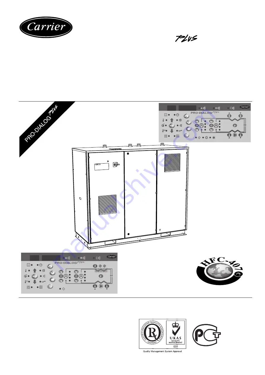
Page 2: ...2 The cover graphics are solely for illustration and forms no part of any offer for sale or any sale contract The manufacturer reserves the right to change the design at any time without notice ...
Page 3: ...e sensors 5 3 5 The controls 6 3 6 Connections at the user s terminal block 6 4 SETTING UP PRO DIALOG PLUS CONTROL 8 4 1 Local interface general features 8 4 2 Unit start stop control 9 4 3 Menus 10 5 PRO DIALOG PLUS CONTROL OPERATION 26 5 1 Start stop control 26 5 2 Heating cooling operation 28 5 3 Evaporator water pump control 28 5 4 Condenser water pump control 28 5 5 Control interlock contact ...
Page 4: ...ndle power cable electrical cables and conduits terminal box covers and motor frames with great care 2 GENERAL DESCRIPTION 2 1 General Pro Dialog is a system for controlling single or dual circuit 30RW water cooled liquid chillers cooling only and heat pump units or 30RWA units with remote condenser Pro Dialog controls compressor start up needed to maintain the desired heat exchanger entering or l...
Page 5: ...igh pressure are used to measure the suction and discharge pressure in each circuit Thermistors The evaporator and condenser option water sensors are installed in the entering and leaving side An optional water system temperature sensor can be used for master slave assembly control in the case of leaving water control For certain options an outdoor temperature sensor or drycooler water temperature...
Page 6: ... 3 11 3 and 3 6 2 The remote setpoint selection contact is only taken into account if the unit is in remote control operating type The remote demand limit selection contact is active whatever the operating type of the unit This contact is mounted in series with the water flow control contact It can be used for any customer safety loop that requires that the unit is stopped if it is open If it is u...
Page 7: ...if it is open If it is unused this contact must be bridged A RS 485 bus is used for connection to the CCN Pin 1 signal Pin 2 ground Pin 3 signal Remarks Volt free contact 24 V a c 48 V d c max 20 V a c or min 20 V d c 3 A max 80 mA min external power supply Connector 4 pin WAGO 734 104 pitch 3 5 One per board needed 24 V a c 20 mA Connector 8 pin WAGO 734 168 pitch 3 5 Connector 3 pin WAGO 231 303...
Page 8: ... be modified INPUTS menu Displays the status of the unit digital and analogue inputs OUTPUTS TESTS menu Displays the status of the unit outputs and enables them to be tested CONFIGURATIONS menu Displays the unit configuration and enables it to be modified ALARMS menu Displays active alarms ALARMS HISTORY menu Displays the history of the alarms OPERATING LOG menu Displays the operating times and nu...
Page 9: ...Press 2 compressor A2 B2 operating hours in h 10 or h 100 4 2 Unit start stop control 4 2 1 Description The unit start stop can be controlled by one of the following methods Locally on the actual unit Local control type By remote control with the aid of user contacts remote control type By CCN control with the aid of the CCN CCN control type The main interface includes a Start Stop button which ca...
Page 10: ... 2 DIGIT DISPLAY Press the MENU button until the LED marked PRESSURE lights 0 0 Press one of the Arrow buttons 1 until the two digit display shows 3 item number 3 2 3 4 3 3 Modifying the value of a parameter access to a sub menu Press the Enter button for more than 2 seconds to enter the modification mode or to select a sub menu This lets you correct the value of an item or select a sub menu with ...
Page 11: ...d The Setpoint menu LED flashes indicating that modification mode is active Keep pressing the Down Arrow button until the value 5 7 is displayed in the four digit display The Setpoint menu LED keeps flashing Press the Enter button again to validate the change The new setpoint is 5 7 C The Setpoint menu LED stops flashing indicating that modification mode no longer applies 4 3 4 Expand display Pres...
Page 12: ...CHEduLE 2 HOLIDAYS HoLidAy HOUR DATE dAtE BROADCAST brodCASt SERVICE 1 SErviCE 1 MASTER SLAVE MAStEr SLAvE HSM HSM PERIOD 3 PEriod 3 PERIOD 4 PEriod 4 PERIOD 5 PEriod 5 PERIOD 6 PEriod 6 PERIOD 7 PEriod 7 PERIOD 8 PEriod 8 PERIOD 1 PEriod 1 PERIOD 2 PEriod 2 HOLIDAYS 3 HoLidAy 3 HOLIDAYS 4 HoLidAy 4 HOLIDAYS 5 HoLidAy 5 HOLIDAYS 6 HoLidAy 7 HOLIDAYS 7 HoLidAy 7 HOLIDAYS 8 HoLidAy 8 HOLIDAYS 15 HoL...
Page 13: ...eset threshold Heating full reset threshold Heating full reset value INPUTS Contact 1 on off Contact 2 heating cooling or heat reclaim Contact 3 demand limit setpoint selection Contact 4 demand limit selection Contact 5 setpoint selection Contact 6 setpoint selection Safety loop status Evaporator water pump operation contact status Condenser water pump operation contact status Fault contact com pr...
Page 14: ...this variable if forced through CCN Start up delay This item indicates the minutes left before the unit can be started This delay at start up is always active after the unit has been switched on The delay can be configured in the User Configuration 1 menu Heating cooling on selection This item is accessible in read write if the unit is in local control mode It is only displayed if the unit is in L...
Page 15: ...he HP protection threshold has been exceeded Circuit has been unloaded and the circuit capacity is not authorised to rise 16 circuit A 17 circuit B Hot gas discharge protection is active In this mode the circuit capacity cannot increase and the circuit may be unloaded The unit unloads when it is in heating mode and the evaporator water temperature goes beyond the authorised thresholds The unit con...
Page 16: ...e unit type and configuration Displayed and used only for dual circuit units See section 3 6 5 for the contact control description Demand limit 3 setpoint Limitation by volt free contact This item is used to define the maximum capacity that the unit is authorised to use if the demand limit contact s activate limit 3 Displayed and used only for dual circuit units See section 3 6 5 for the contact c...
Page 17: ...oint selection section 5 7 for the description of the demand limit function and 3 6 for the description of the connection of contact 3 for single circuit units Dual circuit units this contact is multiplexed with contact 4 to permit the selection of a demand limit point This contact is active in all operating types See section 3 6 5 for the description of this contact and section 5 7 for the descri...
Page 18: ...will remain on until one of the user interface buttons is pressed it is then immediately stopped During the test phase power to the pump is switched on for 10 seconds only When the test is completed the following is displayed Fail displayed if the test has failed because the pump was not started Good displayed if the test was successful and the water flow switch presence contact is closed Evaporat...
Page 19: ...o start the test TESt is displayed on the 4 digit display alternately with the value tested The Outputs Test LED stops flashing Press the Enter key or an arrow key to stop the test 4 3 11 Description of the configuration menu 4 3 11 1 General This menu can be used to display and modify all configura tions Factory Service and User Only the User Configuration can be modified by the end user The Fact...
Page 20: ...s 7 HOLidAy 7 SUB MENU Holidays 8 HOLidAy 8 SUB MENU Holidays 9 HOLidAy 9 SUB MENU Holidays 10 HOLidAy 10 SUB MENU Holidays 11 HOLidAy 11 SUB MENU Holidays 12 HOLidAy 12 SUB MENU Holidays 13 HOLidAy 13 SUB MENU Holidays 14 HOLidAy 14 SUB MENU Holidays 14 HOLidAy 14 SUB MENU Holidays 16 HOLidAy 16 BROADCAST BrodCASt Return to previous menu Broadcast acknowledger selection Broadcast activation Outdo...
Page 21: ...ed until the pause has expired 4 1 0 1 0 Contact 3 select for single circuit units 0 input is used for demand limit command control 1 input is used for dual setpoint command control Determines whether contact 3 is used for remote demand limit or dual setpoint control For single circuit units only 5 0 1 2 0 Cooling setpoint reset select See section 5 6 2 0 reset not selected 1 reset based on outdoo...
Page 22: ...t values 3 1 n1 n2 n3 n4 Night control mode end time 00 00 to 23 59 00 00 Authorises entering the time of day at which the night control mode ends 4 1 0 to 100 Night mode demand limit value Authorises configuration of the maximum capacity authorised during the night mode 5 1 0 or 65 to 99 0 Schedule 1 clock number for unit on off schedule see section 4 3 11 6 0 schedule in local operating mode 65 ...
Page 23: ...ive on the same day the occupied mode takes priority over the unoccupied period Each of the eight periods can be displayed and changed with the aid of a sub sub menu The table below shows how to access the period configuration Method is the same for the time schedule 1 or the time schedule 2 24 23 22 21 P6 P3 20 P3 19 P3 18 P3 P2 P2 17 P4 P4 P3 P2 P2 16 P4 P4 P3 P2 P2 15 P4 P4 P3 P2 P2 14 P4 P4 P3...
Page 24: ...g start minutes to add number of minutes by which the broadcaster will adjust its time for the start of daylight 1 to 1440 minutes saving time 9 nn Daylight saving stop month In this mode you enter the month in which the broadcaster will adjust its time for the end of 1 to 12 daylight saving time 10 nn Daylight saving stop day In this mode you enter the day on which the broadcaster will adjust its...
Page 25: ...ses the following message to be scrolled time of alarm date of alarm full CCN alarm message time of alarm hh mm date dd mm full CCN alarm message up to 64 characters Time and date are displayed if the unit is equipped with an optional CCN clock board 4 3 13 Description of the Alarms History menu ITEM 0 1 2 1 3 1 4 5 1 6 1 7 1 8 9 10 1 11 1 12 1 13 1 14 1 15 1 16 1 17 1 FORMAT nnnn M 10 M100 nnnn M...
Page 26: ...emergency shutdown if this CCN command is activated it shuts the unit down whatever the active operating type General alarm the unit is totally stopped due to failure ITEM 0 1 1 2 1 3 1 4 1 5 1 6 1 7 1 8 1 9 1 FORMAT MAintEnAnCE MEnu ALErt nnn ALErt nnn ALErt nnn ALErt nnn ALErt nnn ALErt nnn ALErt DESCRIPTION When selected this item authorises return to the previous menu Accessible with the Servi...
Page 27: ...N Unoccupied CCN Off Active Disable No Local On Active Occupied Disable No Local On Active On Occupied Dsable No Remote On Active Enable Occupied Disable No CCN On Active Local Occupied Disable No Local On Active On Remote Occupied Disable No Remote On Active Enable CCN Occupied Disable No CCN On PARAMETER STATUS ON OFF CONTROL HEATING COOLING OR HEAT RECLAIM REMOTE HEATING COOLING HC_SEL or OPERA...
Page 28: ...the unit is fitted with two pumps the first pump is started on odd days and the second pump is started on even days Starting the pump periodically for few seconds increases the life time of the pump bearings and the tightness of the pump seal 5 4 Condenser water pump control The unit can control one or two condenser water pumps These pumps can be fixed speed or variable speed pumps Depending on th...
Page 29: ...ing setpoint 3 LOCAL OPERATING MODE PARAMETER STATUS HEATING COOLING OPERATING MODE Cooling Cooling Cooling Cooling Heating Heating Heating Heating Heating CONTROL CONTACT 3 SELECTION Setpoint Setpoint Demand limit Demand limit Setpoint Setpoint Demand limit Demand limit Demand limit CONTROL CONTACT 3 Setpoint 1 Setpoint 2 Setpoint 1 Setpoint 2 SCHEDULE 2 STATUS Occupied Unoccupied Occupied Unoccu...
Page 30: ...ading functions can also affect the temperature control accuracy Compressors are started and stopped in a sequence designed to equalise the number of start ups value weighted by their operating time 5 10 Head pressure control 5 10 1 30RW units in cooling mode The control can regulate the following configurations Drycooler and variable speed condenser pump The fixed fan stages and the pump speed ar...
Page 31: ...herefore to start up the assembly simply validate the Master operating type MASt on the master unit If the Master has been configured for remote control then use the remote volt free contacts for unit start stop The slave unit must stay in CCN operating type continuously To stop the master slave assembly select Local Off LOFF on the master unit or use the remote volt free contacts if the unit has ...
Page 32: ...can be reset depending on the type either automatically on return to normal or manually when action has been taken on the unit Alarms can be reset even if the unit is running This means that an alarm can be reset without stopping the machine In the event of a power supply interrupt the unit restarts automatically without the need for an external com mand However any faults active when the supply i...
Page 33: ...emperature override As above More than 6 successive circuit capacity unloads because of high pressure override As above More than 8 successive circuit capacity unloads because of high discharge temperature As above ACTION TAKEN BY THE CONTROL Compressor is shut down As above As above As above Unit shut down As above As above Unit shut down for heat pumps otherwise no action As above Unit shut down...
Page 34: ...eed pump pump operation contact open Variable speed pump variable speed drive fault As above CCN command received to shutdown the unit The unit is controlled by a System Manager and communication with this module is lost for more than 2 minutes The master slave link is broken due to a loss of communication between the two units for more than 2 minutes All factory parameters are zero Wrong configur...
Page 35: ...35 ...
Page 36: ...6 2004 Supersedes order No 13432 76 03 2002 Manufactured by Carrier s a Montluel France Manufacturer reserves the right to change any product specification without notice Printed in the Netherlands on chlorine free paper ...