CHAPTER 8 TROUBLESHOOTING
8-60
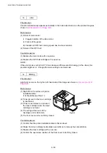
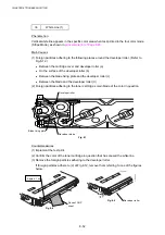
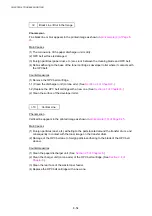
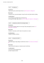
I-19 Mottle
Phenomenon
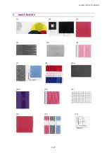
Variation of the scanning density is found in the image as shown in
8-46
.
Main Causes
(1) The transfer unit is not fixed in place.
(2) Assembly of the transfer roller is inaccurate.
(3) THV output of the high-voltage power supply unit is not normal.
(4) Failure of the toner cartridge.
(5) Deformation of the print paper.
Countermeasures
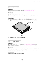
(1) Confirm that the transfer unit is firmly locked in place.
(2) Confirm that the transfer roller is properly installed.
(3) Replace the high-voltage power supply unit with a new one. (See
7
.)
(4) Replace the toner cartridge with a new one.
(5) Replace the paper with new paper from a freshly opened ream.
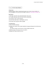
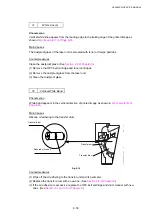
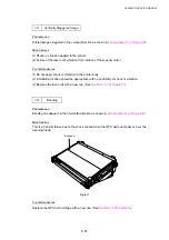
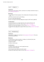
I-20 Residual
Image
Phenomenon
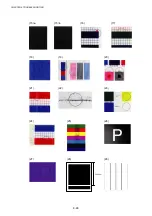
Image of the preceding page appears on every other page as shown in
Page 8-46
.
Main Causes
(1) Cleaning failure due to lifting of the cleaning brush of the drum cleaner.
(2) Contact failure of the drum cleaner’s bias pole.
(3) Failure of the high-voltage power supply unit.
Countermeasures
(1) Check if the drum cleaner is properly installed or not.
(2) Replace the failed high-voltage power supply unit with a new one. (See
Chapter 7
.)
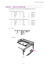
Summary of Contents for HL-3450CN Series
Page 15: ...HL 3450CN SERVICE MANUAL xiii 3 Rating Label For US For Europe 4 Operation Label 5 Jam Label ...
Page 17: ...HL 3450CN SERVICE MANUAL CHAPTER 1 PRODUCT OUTLINE ...
Page 27: ...HL 3450CN SERVICE MANUAL CHAPTER 2 SPECIFICATIONS ...
Page 39: ...CHAPTER 3 INSTALLATION ...
Page 54: ...HL 3450CN SERVICE MANUAL CHAPTER 4 STRUCTURE OF SYSTEM COMPONENTS ...
Page 104: ...HL 3450CN SERVICE MANUAL 4 51 Main PCB Circuit Diagram 1 8 CODE B512137CIR 1 8 LJ8907001 NAME ...
Page 106: ...HL 3450CN SERVICE MANUAL 4 53 Main PCB Circuit Diagram 3 8 CODE B512137CIR 3 8 LJ8907001 NAME ...
Page 108: ...HL 3450CN SERVICE MANUAL 4 55 Main PCB Circuit Diagram 5 8 CODE B512137CIR 5 8 LJ8907001 NAME ...
Page 110: ...HL 3450CN SERVICE MANUAL 4 57 Main PCB Circuit Diagram 7 8 CODE B512137CIR 7 8 LJ8907001 NAME ...
Page 126: ...HL 3450CN SERVICE MANUAL CHAPTER 5 CONTROL PANEL OPERATION ...
Page 173: ...HL 3450CN SERVICE MANUAL CHAPTER 6 PERIODIC MAINTENANCE ...
Page 208: ...CHAPTER 7 DISASSEMBLY RE ASSEMBLY ...
Page 264: ...HL 3450CN SERVICE MANUAL CHAPTER 8 TROUBLESHOOTING ...
Page 310: ...HL 3450CN SERVICE MANUAL 8 47 5 IMAGE FAILURE 1 2 3 4 5 6 7 8 9 a 9 b 10 11 12 13 14 ...
Page 311: ...CHAPTER 8 TROUBLESHOOTING 8 48 15 a 15 b 16 17 18 19 20 21 22 23 24 25 26 27 28 244m m 29 ...

