CHAPTER 5 CONTROL PANEL OPERATION
5-14
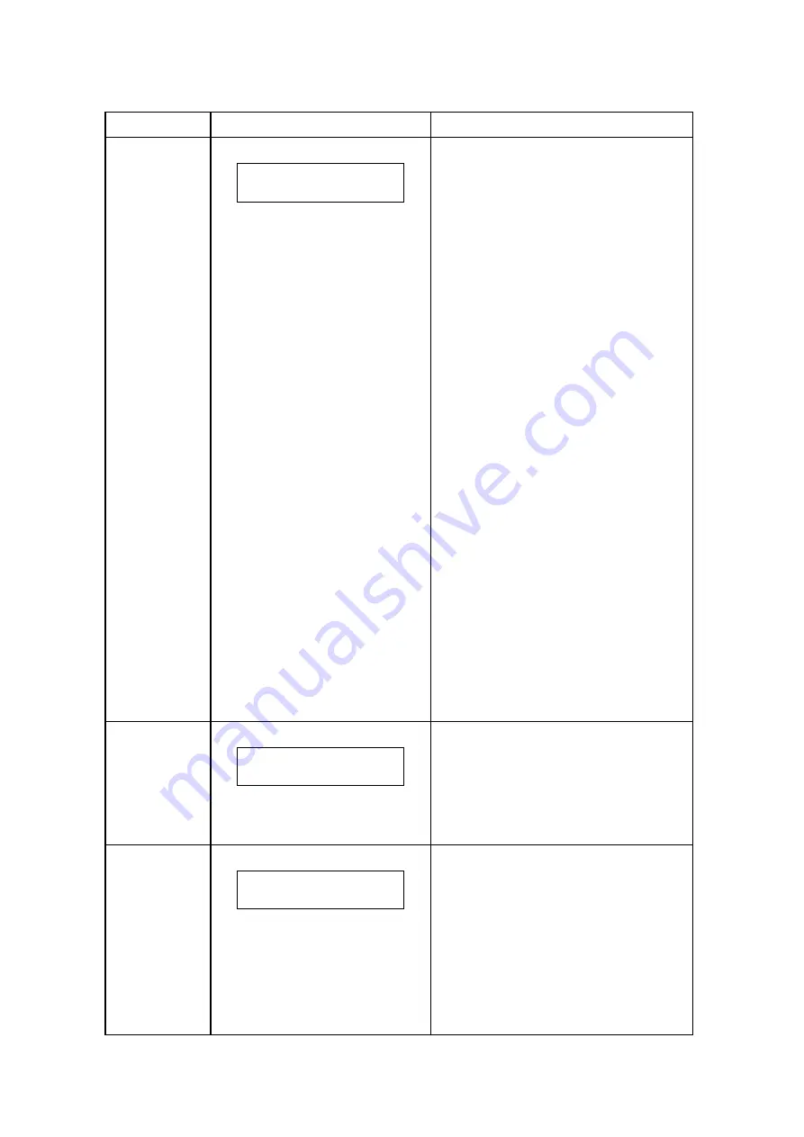
Code No.
LCD Message
Description of Message
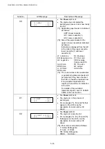
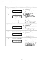
00
00 READY [*1]
[*2 ][*4]
x
The Power LED is lit.
x
The engine has completed the
warming-up process and is now ready
to print.
[*1]: Applicable paper feeder is indicated
as follows;
/UPP: Upper cassette
/LF1: Lower cassette (1)
/LF2: Lower cassette (2)
[*2]: Size of the paper loaded in the
upper or lower cassette is indicated
as follows;
Indication is displayed from the left
in the order of the upper cassette,
lower cassette (1) and lower
cassette (2).
LT: Letter size
DL: Envelope
EX: Executive size PC: Post card
LG: Legal size
CM: Envelope
Commercial #10
A4: A4 size
FR: Free size
B5: B5 size
LD: Ledger
L+: A3 Nobi
A3: A3 size
B4: B4 size
[*4]: The code numbers of consumables
or periodical replacement parts will
be indicated if they have reached
their life or should be replaced now.
If no periodical replacement is
required, there will be no indication
in the LCD.
For details of the periodical
replacement parts, see 36. CLEAR
CARE in the next section.
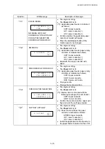
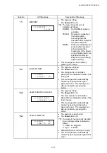
01
01 WAIT [*1]
[*2 ][*4]
x
The Power LED is lit.
x
The engine is in the process of
warming-up.
x
For messages [*1], [*2] and [*4] that
appear on the LCD, see the
description for code number 00
above.
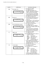
02
02 PRINT [*5][*1]
[*2 ][*4]
x
The Power LED lit.
x
The engine is ready to print.
x
For messages [*1], [*2], [*3] and [*4]
that appear on the LCD, see the
description for code number 00
above.
[*5]: Print color is indicated as follows;
Y: Yellow M: Magenta
C: Cyan K: Black
YM: Yellow & Magenta
YMCK Full
Color
Summary of Contents for HL-3450CN Series
Page 15: ...HL 3450CN SERVICE MANUAL xiii 3 Rating Label For US For Europe 4 Operation Label 5 Jam Label ...
Page 17: ...HL 3450CN SERVICE MANUAL CHAPTER 1 PRODUCT OUTLINE ...
Page 27: ...HL 3450CN SERVICE MANUAL CHAPTER 2 SPECIFICATIONS ...
Page 39: ...CHAPTER 3 INSTALLATION ...
Page 54: ...HL 3450CN SERVICE MANUAL CHAPTER 4 STRUCTURE OF SYSTEM COMPONENTS ...
Page 104: ...HL 3450CN SERVICE MANUAL 4 51 Main PCB Circuit Diagram 1 8 CODE B512137CIR 1 8 LJ8907001 NAME ...
Page 106: ...HL 3450CN SERVICE MANUAL 4 53 Main PCB Circuit Diagram 3 8 CODE B512137CIR 3 8 LJ8907001 NAME ...
Page 108: ...HL 3450CN SERVICE MANUAL 4 55 Main PCB Circuit Diagram 5 8 CODE B512137CIR 5 8 LJ8907001 NAME ...
Page 110: ...HL 3450CN SERVICE MANUAL 4 57 Main PCB Circuit Diagram 7 8 CODE B512137CIR 7 8 LJ8907001 NAME ...
Page 126: ...HL 3450CN SERVICE MANUAL CHAPTER 5 CONTROL PANEL OPERATION ...
Page 173: ...HL 3450CN SERVICE MANUAL CHAPTER 6 PERIODIC MAINTENANCE ...
Page 208: ...CHAPTER 7 DISASSEMBLY RE ASSEMBLY ...
Page 264: ...HL 3450CN SERVICE MANUAL CHAPTER 8 TROUBLESHOOTING ...
Page 310: ...HL 3450CN SERVICE MANUAL 8 47 5 IMAGE FAILURE 1 2 3 4 5 6 7 8 9 a 9 b 10 11 12 13 14 ...
Page 311: ...CHAPTER 8 TROUBLESHOOTING 8 48 15 a 15 b 16 17 18 19 20 21 22 23 24 25 26 27 28 244m m 29 ...

