CHAPTER 4 STRUCTURE OF SYSTEM COMPONENTS
4-40
(3)
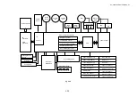
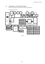
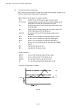
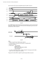
Control of the Fusing Temperature
Each roller of the fusing unit is controlled to maintain the appropriate temperature so
that toner will be fixed correctly onto the print paper.
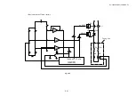
<Basic Structure of Temperature Control (Fig.4-36)>
FLS:
Thyristor to switch the power supply to the heat lamp.
TFU1/TFU2:
Temperature fuse to shut down the circuit for safety when the
temperature becomes too hot within the fixing unit.
TH:
Temperature sensor to detect the surface temperature of the
heat roller (HR).
RY:
Relay to prevent further heating when it becomes hotter than
the set temperature within the fixing unit.
GA/CPU:
Process circuit to control the temperature signal (micro
computer).
CM1:
Sensor circuit for temperature signal (for ACOFF signal).
CM2:
Sensor circuit for temperature signal (for HON signal).
CM3:
Sensor circuit for temperature signal (for processing).
Q:
Sensor circuit for shut-down by the thermistor (for THERR
signal).
HR:
Heat lamp for the heat roller.
BR:
Heat lamp for the back-up roller.
< Signal Functions >
HON-N
To turn on/off the heater inside the fuser roller.
ACOFF
To turn off the relay RY1 if overheat occurs.
THERR
To detect the shut-down by the thermistor.
AD
To convert the temperature sensing signal to AD.
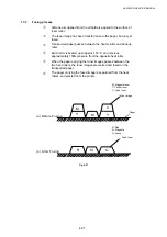
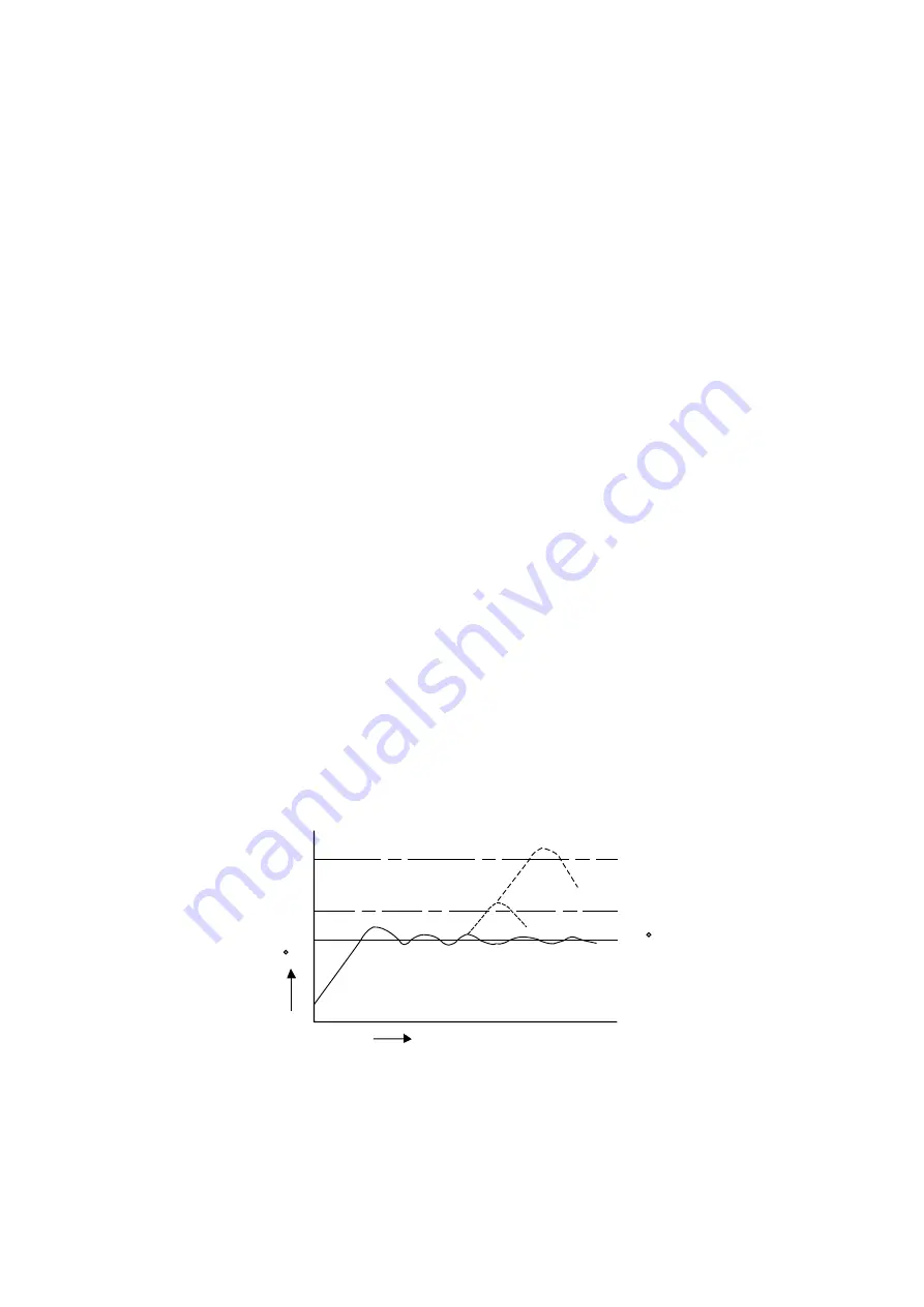
<Controlled Temperature and Safety>
150 TS
TA
TPS
Time
Temperature
( )
C
C
Fig. 4-35
Summary of Contents for HL-3450CN Series
Page 15: ...HL 3450CN SERVICE MANUAL xiii 3 Rating Label For US For Europe 4 Operation Label 5 Jam Label ...
Page 17: ...HL 3450CN SERVICE MANUAL CHAPTER 1 PRODUCT OUTLINE ...
Page 27: ...HL 3450CN SERVICE MANUAL CHAPTER 2 SPECIFICATIONS ...
Page 39: ...CHAPTER 3 INSTALLATION ...
Page 54: ...HL 3450CN SERVICE MANUAL CHAPTER 4 STRUCTURE OF SYSTEM COMPONENTS ...
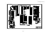
Page 104: ...HL 3450CN SERVICE MANUAL 4 51 Main PCB Circuit Diagram 1 8 CODE B512137CIR 1 8 LJ8907001 NAME ...
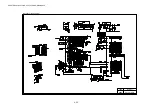
Page 106: ...HL 3450CN SERVICE MANUAL 4 53 Main PCB Circuit Diagram 3 8 CODE B512137CIR 3 8 LJ8907001 NAME ...
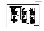
Page 108: ...HL 3450CN SERVICE MANUAL 4 55 Main PCB Circuit Diagram 5 8 CODE B512137CIR 5 8 LJ8907001 NAME ...
Page 110: ...HL 3450CN SERVICE MANUAL 4 57 Main PCB Circuit Diagram 7 8 CODE B512137CIR 7 8 LJ8907001 NAME ...
Page 126: ...HL 3450CN SERVICE MANUAL CHAPTER 5 CONTROL PANEL OPERATION ...
Page 173: ...HL 3450CN SERVICE MANUAL CHAPTER 6 PERIODIC MAINTENANCE ...
Page 208: ...CHAPTER 7 DISASSEMBLY RE ASSEMBLY ...
Page 264: ...HL 3450CN SERVICE MANUAL CHAPTER 8 TROUBLESHOOTING ...
Page 310: ...HL 3450CN SERVICE MANUAL 8 47 5 IMAGE FAILURE 1 2 3 4 5 6 7 8 9 a 9 b 10 11 12 13 14 ...
Page 311: ...CHAPTER 8 TROUBLESHOOTING 8 48 15 a 15 b 16 17 18 19 20 21 22 23 24 25 26 27 28 244m m 29 ...

