CHAPTER 5 CONTROL PANEL OPERATION
5-18
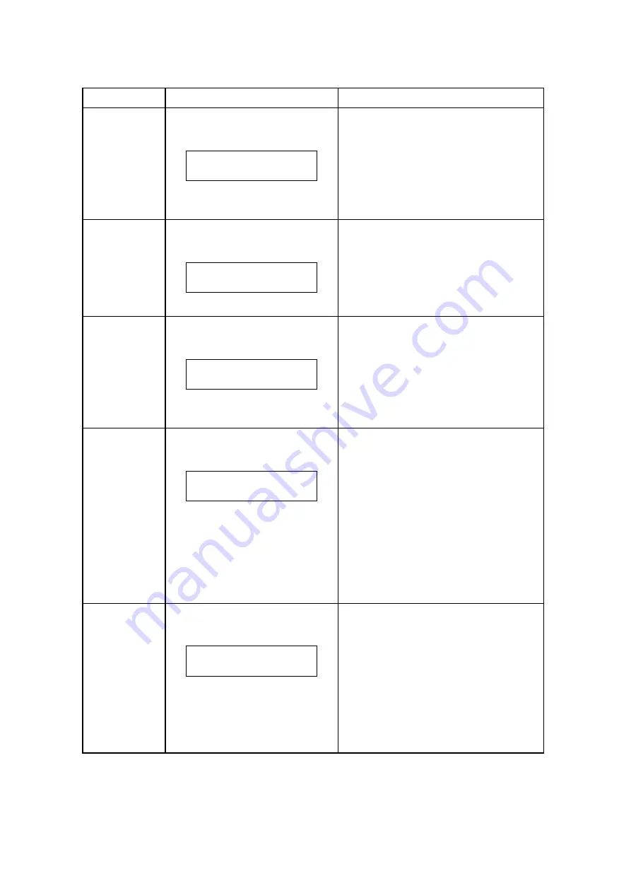
Code No.
LCD Message
Description of Message
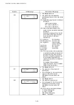
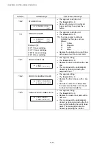
16-4
ALIGN BELT CG
16 ALIGN BELT CG
[*4]
x
The engine is stopped.
x
The Power LED is lit.
x
The OPC belt cartridge is not
installed. Reconfirm the installation
status of the OPC belt cartridge.
x
This message will be automatically
cleared by opening & closing either
the paper exit cover or front cover.
16-5
ALIGN LFU
16 ALIGN LFU
[*4]
x
The engine is ready to print.
x
Turn the power off and connect the
harness between the engine and
fusing unit.
x
Turn the power on. If the warming-up
process starts, it means that proper
connection is now made.
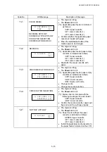
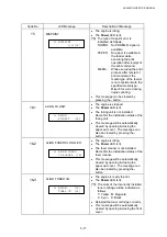
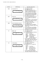
16-6
ALIGN TRANSFER ROLLER
16 ALIGN BELT CG
[*4]
x
The engine is ready to print.
x
The Power LED is lit.
x
The transfer roller is not installed.
Reconfirm the installation status of the
transfer roller.
x
This message will be automatically
cleared by opening & closing either
the paper exit cover or front cover.
17
MEDIA JAM
17 MEDIA JAM
[*7] [*4]
x
The engine is stopped.
x
The Power LED is lit.
[*7]: The kind of jam (location of jam) is
indicated as follows;
FEED:
Paper
feeder
INNER:
Inside of the printer
OUTER: Paper exit unit
DRUM:
Transfer drum
DPL:
Inside the duplex unit
x
This message can be cleared by
pressing the - button after opening &
closing the front cover, back cover
and paper exit cover.
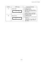
18
CLOSE PANEL
18 CLOSE PANEL
[*8] [*4]
x
The engine is ready to print.
x
The Power LED is lit.
[*8]: The open cover is indicated as
follows;
FRONT:
Front
cover
TOP:
Paper exit cover
REAR:
Rear access cover
DPL:
Rear access cover
LFU:
Fusing unit cover
x
This message can be cleared by
opening & closing the indicated cover.
Summary of Contents for HL-3450CN Series
Page 15: ...HL 3450CN SERVICE MANUAL xiii 3 Rating Label For US For Europe 4 Operation Label 5 Jam Label ...
Page 17: ...HL 3450CN SERVICE MANUAL CHAPTER 1 PRODUCT OUTLINE ...
Page 27: ...HL 3450CN SERVICE MANUAL CHAPTER 2 SPECIFICATIONS ...
Page 39: ...CHAPTER 3 INSTALLATION ...
Page 54: ...HL 3450CN SERVICE MANUAL CHAPTER 4 STRUCTURE OF SYSTEM COMPONENTS ...
Page 104: ...HL 3450CN SERVICE MANUAL 4 51 Main PCB Circuit Diagram 1 8 CODE B512137CIR 1 8 LJ8907001 NAME ...
Page 106: ...HL 3450CN SERVICE MANUAL 4 53 Main PCB Circuit Diagram 3 8 CODE B512137CIR 3 8 LJ8907001 NAME ...
Page 108: ...HL 3450CN SERVICE MANUAL 4 55 Main PCB Circuit Diagram 5 8 CODE B512137CIR 5 8 LJ8907001 NAME ...
Page 110: ...HL 3450CN SERVICE MANUAL 4 57 Main PCB Circuit Diagram 7 8 CODE B512137CIR 7 8 LJ8907001 NAME ...
Page 126: ...HL 3450CN SERVICE MANUAL CHAPTER 5 CONTROL PANEL OPERATION ...
Page 173: ...HL 3450CN SERVICE MANUAL CHAPTER 6 PERIODIC MAINTENANCE ...
Page 208: ...CHAPTER 7 DISASSEMBLY RE ASSEMBLY ...
Page 264: ...HL 3450CN SERVICE MANUAL CHAPTER 8 TROUBLESHOOTING ...
Page 310: ...HL 3450CN SERVICE MANUAL 8 47 5 IMAGE FAILURE 1 2 3 4 5 6 7 8 9 a 9 b 10 11 12 13 14 ...
Page 311: ...CHAPTER 8 TROUBLESHOOTING 8 48 15 a 15 b 16 17 18 19 20 21 22 23 24 25 26 27 28 244m m 29 ...

