HL-3450CN SERVICE MANUAL
4-25
1.6
Paper Transportation System
1.6.1
Outline
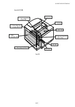
This printer employs automatic paper feeding from the media cassette.
When toner images are formed on the transfer drum through the operations of the print
system and transfer system, paper is fed by the pick-up roller and transported to the
register roller. The transported paper is further transported to the transfer, fuser and
exit parts by the register roller synchronizing with the rotation of the transfer drum.
1.6.2
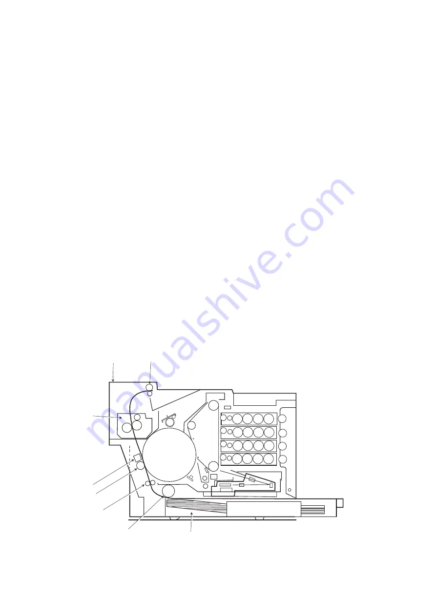
Structure of paper transportation system
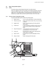
The paper transportation system consists of the following parts;
c
Media cassette:
Case to accommodate paper to be fed automatically.
d
Paper pick-up roller:
Roller to feed sheets of paper one by one, preventing
multi-feed.
e
Register roller:
Roller to transport papers synchronized with the
transfer drum.
f
Transfer part:
Print processing part consisting of transfer drum and
transfer roller to transfer the toner image onto the
paper.
g
Paper discharger unit:
Corona generator to generate AC corona for
separating paper from the transfer drum.
h
Fusing unit:
Mechanical part to fuse the toner image with heat
rollers and fix it on the paper.
i
Paper exit unit:
Mechanical part to exit the fused paper from the
printer.
j
Paper exit roller:
Roller to feed paper from the printer.
K
Y
M
C
Fig. 4-25
j
d
e
f
g
h
i
c
Summary of Contents for HL-3450CN Series
Page 15: ...HL 3450CN SERVICE MANUAL xiii 3 Rating Label For US For Europe 4 Operation Label 5 Jam Label ...
Page 17: ...HL 3450CN SERVICE MANUAL CHAPTER 1 PRODUCT OUTLINE ...
Page 27: ...HL 3450CN SERVICE MANUAL CHAPTER 2 SPECIFICATIONS ...
Page 39: ...CHAPTER 3 INSTALLATION ...
Page 54: ...HL 3450CN SERVICE MANUAL CHAPTER 4 STRUCTURE OF SYSTEM COMPONENTS ...
Page 104: ...HL 3450CN SERVICE MANUAL 4 51 Main PCB Circuit Diagram 1 8 CODE B512137CIR 1 8 LJ8907001 NAME ...
Page 106: ...HL 3450CN SERVICE MANUAL 4 53 Main PCB Circuit Diagram 3 8 CODE B512137CIR 3 8 LJ8907001 NAME ...
Page 108: ...HL 3450CN SERVICE MANUAL 4 55 Main PCB Circuit Diagram 5 8 CODE B512137CIR 5 8 LJ8907001 NAME ...
Page 110: ...HL 3450CN SERVICE MANUAL 4 57 Main PCB Circuit Diagram 7 8 CODE B512137CIR 7 8 LJ8907001 NAME ...
Page 126: ...HL 3450CN SERVICE MANUAL CHAPTER 5 CONTROL PANEL OPERATION ...
Page 173: ...HL 3450CN SERVICE MANUAL CHAPTER 6 PERIODIC MAINTENANCE ...
Page 208: ...CHAPTER 7 DISASSEMBLY RE ASSEMBLY ...
Page 264: ...HL 3450CN SERVICE MANUAL CHAPTER 8 TROUBLESHOOTING ...
Page 310: ...HL 3450CN SERVICE MANUAL 8 47 5 IMAGE FAILURE 1 2 3 4 5 6 7 8 9 a 9 b 10 11 12 13 14 ...
Page 311: ...CHAPTER 8 TROUBLESHOOTING 8 48 15 a 15 b 16 17 18 19 20 21 22 23 24 25 26 27 28 244m m 29 ...

