


2001/10/02
CHAPTER 4 HP-GL/2 - 23
•
The following
flags
are used:
':' -
Select pen. The number which follows is the required pen number. A PE command that does not
include a select pen command uses the currently selected pen.
'<' - Pen up. The pen is raised and moved to the specified coordinate pair. All coordinate pair values
not preceded by this flag are automatically interpreted as pen down plotting commands.
'>' - Fractional data. The value following the flag specifies the number of fractional binary bits in the
coordinate data.
'=' - Absolute plotting mode. The pair of coordinates which follow this flag are absolute coordinates.
'7' - 7 bit mode. All subsequent coordinate values within this PE command are to be interpreted as 7-bit
values, that is, encoded in base 32.
•
If you use the ':'
flag
in polygon mode it is ignored as the SP command has no effect in this mode.
•
Values and coordinates are encoded in base 64 or base 32. Values determine the setting of the immediately
preceding
flag
. Legal values and coordinates are as follows:
Pen number -
0 (white) or 1(black)
Number of fractional binary bits -
-26 to 26. The default is 0.
x- and y -coordinates -
(-230) to 230 - 1 current units. If the pen position is moved
outside this range, subsequent plotting commands are ignored
until an absolute coordinate pair within the allowable range is
specified.
•
Flag
and coordinate values are encoded as either base 64 or base 32 numbers and then transmitted as ASCII
character codes. Base 64 is the default. Use Base 64 if your computer can send data without a parity bit.
Use base 32 if your system requires a parity bit.
•
To encode an integer proceed as follows. If the number is negative, take the absolute value, multiply by
2 and add 1. Hence -x : = 2x+1. If the number is positive simply multiply by 2. Hence x :=2x. Convert
the new number into base 64 or base 32 according to your system and encode each base 64 or base 32 digit
as the corresponding ASCII character.
•
To encode a real number proceed as follows. Multiply the number of decimal places in your coordinate's
data by 3.33 and round the result up to the next highest integer (for example round 6.66 up to 7). This gives
the number of binary bits needed to represent the number's fractional part - the value that you will supply with
the '>' flag. Call this number n. Now multiply the number you are encoding by 2
n
. Round this number to
the nearest integer and then follow the procedure described above for encoding an integer.
•
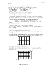
Transmit each number to the printer least significant digits first. Terminate each number with the most
significant digit. This must be specified from a different ASCII range from the preceding digits in the
number. In base 64, non-terminating digits are represented by the numbers 63-126 and terminating digits by
the numbers 191-254. In base 32, non-terminating digits are represented by the numbers 63-94 and
terminating digits by the numbers 95-126. Hence if using a base 32 number whose least significant digit is
14, and whose most significant digit is 5, encode 14 as 77 (63+14) and 5 as 100 (95+5).
Non-terminator
Terminator
Base 64
63-126
191-254
Base 32
63-94
95-126
•
In symbol mode the PE command draws the specified symbol at each specified point.
•
In polygon mode the points specified within the PE command are not plotted. Instead they are stored in the
polygon buffer and used when a FP (Fill Polygon) or EP (Edge Polygon) command is used.
•
The PE command with no parameters simply updates the carriage return point.
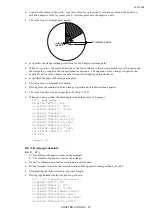
CI - Circle plot
CI
r
(,
qd
)[;]
r
; Radius of circle ( in current units )
qd
; Chord angle ( in degrees )
•
The command plots a circle with the current position as the centre, with a radius r and chord angle qd.
•
After plotting, the cursor returns to the centre of the circle.
•
Plotting takes place irrespective of whether the pen is up or down.
•
Valid values for r are specified in the current unit.
•
Valid values for
qd
are clamped real numbers in the range 0.5° to 180°. The default value is 5°.
Summary of Contents for HL-1250
Page 15: ...2001 10 02 CHAPTER 1 INTRODUCTION 1 CHAPTER 1 INTRODUCTION ...
Page 20: ...2001 10 02 CHAPTER 1 INTRODUCTION 6 ...
Page 21: ...2001 10 02 CHAPTER 2 PCL 1 CHAPTER 2 PCL PRINTER CONTROL LANGUAGE ...
Page 59: ...2001 10 02 CHAPTER 2 PCL 39 ...
Page 76: ...2001 10 02 CHAPTER 2 PCL 56 ...
Page 104: ...2001 10 02 CHAPTER 2 PCL 84 71 71 Lines picture Same as above ...
Page 109: ...2001 10 02 CHAPTER 2 PCL 89 ...
Page 123: ...2001 10 02 CHAPTER 2 PCL 103 ...
Page 131: ...2001 10 02 CHAPTER 3 PCL5C 1 CHAPTER 3 PCL5C ...
Page 149: ...2001 10 02 CHAPTER 4 HP GL 2 1 CHAPTER 4 HP GL 2 GRAPHICS LANGUAGE ...
Page 199: ...2001 10 02 CHAPTER 4 HP GL 2 51 ...
Page 204: ...2001 10 02 CHAPTER 4 HP GL 2 56 ...
Page 205: ...2001 10 02 CHAPTER 5 PJL 1 CHAPTER 5 PJL PRINTER JOB LANGUAGE ...
Page 248: ...2001 10 02 CHAPTER 5 PJL 44 ...
Page 263: ...2001 10 02 CHAPTER 5 PJL 59 ...
Page 264: ...2001 10 02 CHAPTER 6 EPSON 1 CHAPTER 6 EPSON FX 850 ...
Page 286: ...2001 10 02 CHAPTER 6 EPSON 23 LPRINT CHR 27 CHR 37 CHR 1 CHR 0 Select downloaded characters ...
Page 290: ...2001 10 02 CHAPTER 6 EPSON 27 Sample 12 ...
Page 292: ...2001 10 02 CHAPTER 6 EPSON 29 Sample 14 ...
Page 294: ...2001 10 02 CHAPTER 7 IBM PROPRINTER 1 CHAPTER 7 IBM PROPRINTER XL ...
Page 315: ...2001 10 02 CHAPTER 7 IBM PROPRINTER 22 ...
Page 316: ...2001 10 02 CHAPTER 8 BAR CODE CONTROL 1 CHAPTER 8 BAR CODE CONTROL ...
Page 326: ...2001 10 02 CHAPTER 9 HP GL 1 CHAPTER 9 HP GL GRAPHICS LANGUAGE ...
Page 353: ...10 5 2001 APPENDIX A COMPARISON LIST 1 APPENDIX A COMPARISON LIST ...
Page 391: ...10 5 2001 APPENDIX A COMPARISON LIST 39 AUTOSKIP ON OFF ON OFF ON OFF ON OFF ...


