


2001/10/02
CHAPTER 3 "PCL5C" - 12
4.
COLOR GRAPHICS
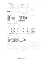
4.1.
Start Raster Transfer
Command
ESC*r#A (27)(42)(114)#(65) <1Bh><2Ah><72h>#<41h>
# = 0 *
Prints the image from the left edge of the logical page.
= 1
Prints the image from the current cursor position.
= 2
Executes scaling. Prints the image from the left edge of the logical page.
= 3
Executes scaling. Prints the images from the current cursor position.
* Default value = 0
•
This command signals the start of the transfer of raster image data to the printer.
•
The transfer of raster data to the printer continues until either an
End Raster Transfer
command is sent or a
command other than
Send Raster Data
,
Set Compression Mode
or
Y-Offset
is sent.
•
The source width and height are set by the
Set Raster Area Width
(
ESC*r#S
) and
Set Raster Area Height
(
ESC*r#T
) commands. When the # value is 2 or 3, the data with these source width/height values is
enlarged or reduced to the width and height set by the
Set Destination Raster Width
and
Set Destination
Raster Height
commands. (Refer to the following sections.)
4.2.
Set Destination Raster Width
Command
ESC*t#H (27)(42)(116)#(72) <1Bh><2Ah><74h>#<48h>
Range = 0 ~ 32767 (number of decipoints in 1/720”)
Default value = 0
•
If value 2 or 3 is sent with the
Start Raster Transfer
command and graphic scaling is set, this command sets
the destination width.
•
Values outside the range are invalid.
•
If the setting is 0 or is omitted, this command uses the same width as the source width.
•
If the specified width is wider than the page, drawings are clipped by the right physical page boundary. The
scaling factor is dealt with correctly.
4.3.
Set Destination Raster Height
Command
ESC*t#V (27)(42)(116)#(86) <1Bh><2Ah><70h>#<56h>
Range = 0 ~ 32767 (number of decipoints in 1/720”)
Default value = 0
•
If value 2 or 3 is sent with the
Start Raster Transfer
command and graphic scaling is set, this command sets
the destination height.
•
Values outside the range are invalid.
•
If the setting is 0 or is omitted, this command uses the same height as the source height.
•
If the specified height is longer than the page, drawings are clipped by the bottom of physical page boundary.
The scaling factor is dealt with correctly.
Summary of Contents for HL-1250
Page 15: ...2001 10 02 CHAPTER 1 INTRODUCTION 1 CHAPTER 1 INTRODUCTION ...
Page 20: ...2001 10 02 CHAPTER 1 INTRODUCTION 6 ...
Page 21: ...2001 10 02 CHAPTER 2 PCL 1 CHAPTER 2 PCL PRINTER CONTROL LANGUAGE ...
Page 59: ...2001 10 02 CHAPTER 2 PCL 39 ...
Page 76: ...2001 10 02 CHAPTER 2 PCL 56 ...
Page 104: ...2001 10 02 CHAPTER 2 PCL 84 71 71 Lines picture Same as above ...
Page 109: ...2001 10 02 CHAPTER 2 PCL 89 ...
Page 123: ...2001 10 02 CHAPTER 2 PCL 103 ...
Page 131: ...2001 10 02 CHAPTER 3 PCL5C 1 CHAPTER 3 PCL5C ...
Page 149: ...2001 10 02 CHAPTER 4 HP GL 2 1 CHAPTER 4 HP GL 2 GRAPHICS LANGUAGE ...
Page 199: ...2001 10 02 CHAPTER 4 HP GL 2 51 ...
Page 204: ...2001 10 02 CHAPTER 4 HP GL 2 56 ...
Page 205: ...2001 10 02 CHAPTER 5 PJL 1 CHAPTER 5 PJL PRINTER JOB LANGUAGE ...
Page 248: ...2001 10 02 CHAPTER 5 PJL 44 ...
Page 263: ...2001 10 02 CHAPTER 5 PJL 59 ...
Page 264: ...2001 10 02 CHAPTER 6 EPSON 1 CHAPTER 6 EPSON FX 850 ...
Page 286: ...2001 10 02 CHAPTER 6 EPSON 23 LPRINT CHR 27 CHR 37 CHR 1 CHR 0 Select downloaded characters ...
Page 290: ...2001 10 02 CHAPTER 6 EPSON 27 Sample 12 ...
Page 292: ...2001 10 02 CHAPTER 6 EPSON 29 Sample 14 ...
Page 294: ...2001 10 02 CHAPTER 7 IBM PROPRINTER 1 CHAPTER 7 IBM PROPRINTER XL ...
Page 315: ...2001 10 02 CHAPTER 7 IBM PROPRINTER 22 ...
Page 316: ...2001 10 02 CHAPTER 8 BAR CODE CONTROL 1 CHAPTER 8 BAR CODE CONTROL ...
Page 326: ...2001 10 02 CHAPTER 9 HP GL 1 CHAPTER 9 HP GL GRAPHICS LANGUAGE ...
Page 353: ...10 5 2001 APPENDIX A COMPARISON LIST 1 APPENDIX A COMPARISON LIST ...
Page 391: ...10 5 2001 APPENDIX A COMPARISON LIST 39 AUTOSKIP ON OFF ON OFF ON OFF ON OFF ...


