
3-32
Confidential
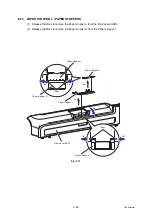
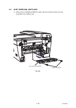
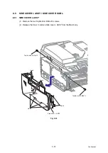
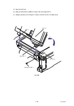
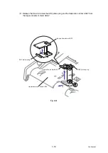
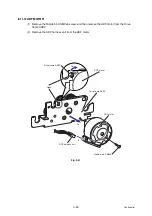
8.9.2
SIDE COVER SUB L
(1) Remove the Taptite bind B M4x12 screw.
(2) Release the Hook to remove the Side cover sub L from the Side cover L ASSY.
Fig. 3-25
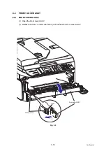
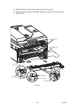
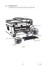
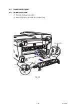
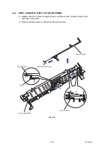
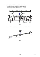
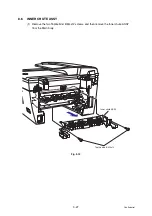
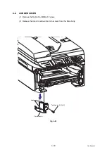
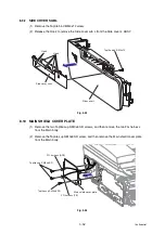
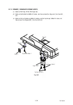
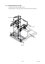
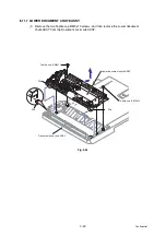
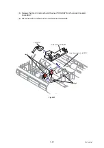
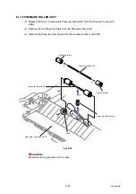
8.10 MAIN SHIELD COVER PLATE
(1) Remove the two Taptite cup S M3x6 SR screws, and then remove the two FG harness
from the Main body.
(2) Remove the Taptite cup S M3x6 SR screw, and then remove the Main shield cover plate
from the Main body.
Fig. 3-26
Taptite bind B M4x12
Side cover sub L
Hook
Hook
Side cover L
Taptite cup S M3x6 SR
Taptite cup S M3x6 SR
FG harness (ADF)
FG harness (FB)
Main shield cover plate
Summary of Contents for DCP-7030
Page 201: ...5 5 Confidential Print sample Fig 5 1 ...
Page 226: ...5 30 Confidential Location of fans Fig 5 13 Fan motor 60 unit Right side ...
Page 234: ...6 2 Confidential LVPS PCB Circuit Diagram 100V ...
Page 235: ...6 3 Confidential LVPS PCB Circuit Diagram 200V ...
Page 239: ...6 7 Confidential Wiring Diagram ...