003002_20000112.doc
1 Doc.# 003002
01/12/00
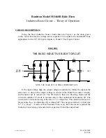
Bonitron Model M3460R Ride-Thru
Inductive Boost Circuit - Theory of Operation
CIRCUIT DESCRIPTION:
Using the basic inductive boost circuit shown in Figure 1 as the main power
source for an inverter, the voltage across capacitor C2 is equal to the nominal DC bus
appropriate for the 3
∅
AC input at inputs A, B and C. See Figure 1 below.
FIGURE 1
Vin
NOTE: THE VALUE OF C1 IS SMALL COMPARED TO C2
THE BASIC INDUCTIVE BOOST CIRCUIT
C
3 AC
∅
INPUT
B
A
C1
C2
Q1
L1
D1
Vout
If the input voltage dips, the output voltage would tend to follow the input at the
same ratio. A drop in the output voltage is sensed in the Ride-Thru control circuitry
and transistor Q1 is turned 'on'. The D1 diode is then in a blocking mode and the
current in inductor L1 starts to increase due to the conduction of transistor Q1. The
current in L1 starts increasing at the rate of
V
in
/
L1
Amps/Sec. The current increases to a
preset value, 'I
max
', at which time Q1 is turned 'off'. The energy stored in L1 at this time
is
(L1)
/
2
x '(I
max
)
2
' = Joules or Watt-Seconds. Thus, every time the circuit is pulsed, the
'inductive boost' energy is transferred to capacitor C2 and the output load.
Summary of Contents for M3460R
Page 11: ...990078_19990803 doc ...
Page 22: ...970066P_19991230 doc ...
Page 23: ...980265P_19991230 doc ...
Page 25: ...990256_19991022 doc ...
Page 27: ...000122_20000425 doc ...
Page 29: ...990036_19990827 doc ...
Page 30: ...970104_19991025 doc ...
Page 31: ...970103_19981028 doc ...
Page 32: ...990026_19991021 doc ...
Page 33: ...990243_20000712 doc IGBT 150A 1200V IGBT 150A 1200V 150A 1200V IGBT 150A 1200V IGBT ...
Page 34: ...990244_20000712 doc ...
Page 35: ...980233_20000725 doc ...
Page 36: ...970200_20000718 doc ...
Page 37: ... SYSTEM NOTES ...


