


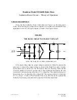


BONITRON MODEL 3460 RIDE THRU
Field installation procedure for rack systems
993002_19991022.doc
doc.# 993002
10/22/99
Procedure:
1. Check the Ride-Thru for shipping damage such as loose screws and unseated connectors.
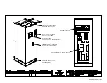
2. Determine wiring conduit access and modify access panels as needed.
•
Use Bonitron drawing # 990163 for access panel removal and modification details
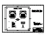
3. Connect 3-phase input AC to L1, L2, & L3 terminals of the Ride-Thru disconnect panel.
Connect ground wire to the terminal provided at the lower left side of the disconnect panel.
•
Use document # 993004 to aid in wire sizing
•
Use appropriate Bonitron
"Customer Connections & Component ID"
drawing and
"Rack
Disconnect Panel Layout"
drawings for connection points
4. Connect DC bus from inverter, to DC+ and DC- terminals of the Ride-Thru disconnect panel.
Ensure polarity is correct.
•
Use document # 993004 to aid in wire sizing
•
Use appropriate Bonitron
"Customer Connections & Component ID"
drawing and
"Rack
Disconnect Panel Layout"
drawings for connection points
5. Ensure all terminal safety covers are installed over AC and DC terminals.
6. Connect shunt trip wiring to the Bonitron Ride-Thru disconnect panel.
•
Refer to Bonitron
Example Of Shunt Trip Coil Wiring
drawing # 990009 for connection
•
Use appropriate Bonitron
"Customer Connections & Component ID"
drawing and
"Rack
Disconnect Panel Layout"
drawings for connection points
7. Connect system monitoring (DCS) wiring. I/O signal data and logic states are outlined in
section 3 of the Ride-Thru Customer Reference Manual.
•
Fault contacts can be wired according to various connection schemes. Refer to all
existing system connection and fault logic drawings
•
Use appropriate Bonitron
"Customer Connections & Component ID"
drawing and
"Rack
Disconnect Panel Layout"
drawings for connection points
•
If DCS is not used or another run signal is not used, be sure that a jumper is installed
across terminals 9 & 10 of TS2, (run command) on the 4460C board.
This completes the installation procedure.
Summary of Contents for M3460R
Page 11: ...990078_19990803 doc ...
Page 22: ...970066P_19991230 doc ...
Page 23: ...980265P_19991230 doc ...
Page 25: ...990256_19991022 doc ...
Page 27: ...000122_20000425 doc ...
Page 29: ...990036_19990827 doc ...
Page 30: ...970104_19991025 doc ...
Page 31: ...970103_19981028 doc ...
Page 32: ...990026_19991021 doc ...
Page 33: ...990243_20000712 doc IGBT 150A 1200V IGBT 150A 1200V 150A 1200V IGBT 150A 1200V IGBT ...
Page 34: ...990244_20000712 doc ...
Page 35: ...980233_20000725 doc ...
Page 36: ...970200_20000718 doc ...
Page 37: ... SYSTEM NOTES ...