Doc.# 993014
07/25/2000
3.4.2 Precharge Complete Output
The Precharge Complete output is an isolated, open collector transistor output, which will be ON when the
DC bus has reached a level of 560VDC, and the Run command is closed. The connections are located on
terminals 7 (-) and 8 (+) of 4460C1 connector TS2.
3.4.3 Ride-Thru Ready Output
The Ride-Thru Ready output is an isolated open collector transistor output, which will be ON when the
Ride-Thru is fully operational and capable of regulating the DC bus voltage under the rated power dip
conditions. The connections are located on terminals 5 (-) and 6 (+) of 4460C1 connector TS2. This signal
is also provided to the 3460M1 Fault Multiplex board (see 3.4.7).
If any 1 of 4 booster stages fails and blows its fuse, the Ride-Thru Ready output will turn OFF and the
Blown Fuse LED (3460C1 Ride-Thru Control board) will turn ON. An LED above the blown fuse on one
or more of the 3438F3 Blown Fuse Detector boards will turn ON. The other boost chopper stages will
continue to operate as required.
3.4.4 Ride-Thru Active Output
The Ride-Thru Active output is an isolated, open collector transistor output which will be ON when the
Ride-Thru section is regulating the DC bus voltage under a input line dip condition. The connections are
located on terminals 3 (-) and 4 (+) of 4460C1 connector TS2.
3.4.5 Voltage Dip Sensor Output
The voltage dip sensor output is an isolated, open collector transistor, which will be OFF if the AC line dips
below the AC voltage dip setpoint or if any single phase is missing. The connections are located on
terminals 13 (-) and 14 (+) of 4460C1 connector TS2. This signal is also provided to the 3460M1 Fault
Multiplex board (see 3.4.7).
3.4.6 Temperature Sensor Output
The temperature sensor output is an isolated, open collector transistor output, which will be OFF when the
backplate temperature exceeds 130
°
F. The connections are located on terminals 1 (-) and 2 (+) of 4460C1
connector TS2. This signal is also provided to the 3460M1 Fault Multiplex board (see 3.4.7).
3.4.7 Multiplexed Fault Output
The 3460M1Fault Multiplex board receives the AC Voltage Dip, Over-Temp, and Ride-Thru Ready
signals. When any one of these signals indicates a problem, the Fault contact will change states. Both N.O.
and N.C. contacts are available at TS2 of the 3460M1 board.
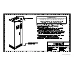
4. Mechanical Description
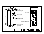
The entire Ride-Thru system is mounted in a UL508 type-12, NEMA/EEMAC type-12 electrical cabinet
measuring approximately 800mm(W) X 600mm(D) X 2000mm(H) enclosed rack with a 100mm(H) plinth.
The Ride-Thru module, customer power connections, and power disconnects are mounted on the back
panel of the cabinet. Conduit access for wiring is available from either the top or bottom of the cabinet. The
disconnect actuator and the display panel are located on the front of the cabinet. Refer to the
Ride-Thru
Cabinet Dimensional Outline
drawing and the
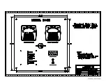
Conduit Access Modification Details
drawing for details.
5. Environmental
The maximum temperature within the rack should be 50
°
Celsius. Non-Condensing, filtered air may be
required to cool the rack.
Summary of Contents for M3460R
Page 11: ...990078_19990803 doc ...
Page 22: ...970066P_19991230 doc ...
Page 23: ...980265P_19991230 doc ...
Page 25: ...990256_19991022 doc ...
Page 27: ...000122_20000425 doc ...
Page 29: ...990036_19990827 doc ...
Page 30: ...970104_19991025 doc ...
Page 31: ...970103_19981028 doc ...
Page 32: ...990026_19991021 doc ...
Page 33: ...990243_20000712 doc IGBT 150A 1200V IGBT 150A 1200V 150A 1200V IGBT 150A 1200V IGBT ...
Page 34: ...990244_20000712 doc ...
Page 35: ...980233_20000725 doc ...
Page 36: ...970200_20000718 doc ...
Page 37: ... SYSTEM NOTES ...


