D3460R.CMAN.V4CAB1150AX.02
7/26/2000
TABLE OF CONTENTS
Description
Doc.#
(Rev. Date)
Pg
Model M3460R Cabinet Mounted Ride-Thru System Operation Manual
993014
(07/25/00)
2
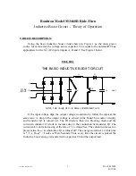
Model M3460R Ride-Thru Inductive Boost Circuit Theory Of Operation
003002
(01/12/00)
8
Inspection And Unpacking Instructions
990078
(08/03/99) 10
Field Installation Procedure For Rack Systems
993002
(10/22/99) 11
Conduit Access Modification Details
990163
(08/04/99) 12
Recommended Input Power Wiring Sizes And Power Source Fusing For Model M3460R Cabinet
Mounted Ride-Thru Systems
993004
(07/18/00) 13
Field Start-up Procedure For Rack Systems
993001
(10/22/99) 14
Ride-Thru Power Threshold Voltage Adjustment Procedure
985001
(07/21/00) 16
Ride-Thru Module Individual Stage Verification Procedure
993003
(06/29/00) 19
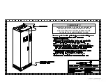
Typical Ride-Thru Cabinet Features and Dimensional Outline
000200
(07/13/00) 20
Option “A2” Display Panel Dimensional Outline and Layout Drawing
970066P
(12/30/99)
21
Option “A4” Display Panel Dimensional Outline and Layout Drawing
980265P
(12/30/99)
22
Ride-Thru Rack Disconnect Panel Layout
990255
(10/22/99)
23
Typical “R1” Chassis Ride-Thru Module With Metering and PLC Interface Dimensional Outline
990256
(10/22/99)
24
Typical Ride-Thru Cabinet Customer Connections and Internal Component ID Drawing
000199
(07/12/00) 25
Basic Ride-Thru and Inverter Power Interconnection
000122
(04/25/00) 26
Example of Shunt Trip Coil Wiring
990009
(06/20/00) 27
Example of Fault Output Wiring
990036
(08/27/99) 28
Ride-Thru Rack Disconnect Panel Wiring Diagram
970104
(10/25/99)
29
Option “A2” Display Panel and Status Monitor PLC Interface Wiring
970103
(10/28/98)
30
Option “A4” Display Panel and Status Monitor PLC Interface Wiring
990026
(10/21/99)
31
(M3460R-4R1-150C2) 460VAC/150KW Ride-Thru Module Control Wiring Diagram
990243
(07/12/00)
32
(M3460R-4R1-150C2) 460VAC/150KW Ride-Thru Module Power Section Wiring Diagram
990244
(07/12/00)
33
Typical Ride-Thru Cabinet System Basic Signal Flow Diagram
990259
(12/30/99)
34
Typical Ride-Thru Cabinet System Diagnostic Signal Connections Diagram
980233
(07/25/00)
35
Ride-Thru Module Removal Information for Service or Replacement
970200
(07/18/00)
36
Summary of Contents for M3460R
Page 11: ...990078_19990803 doc ...
Page 22: ...970066P_19991230 doc ...
Page 23: ...980265P_19991230 doc ...
Page 25: ...990256_19991022 doc ...
Page 27: ...000122_20000425 doc ...
Page 29: ...990036_19990827 doc ...
Page 30: ...970104_19991025 doc ...
Page 31: ...970103_19981028 doc ...
Page 32: ...990026_19991021 doc ...
Page 33: ...990243_20000712 doc IGBT 150A 1200V IGBT 150A 1200V 150A 1200V IGBT 150A 1200V IGBT ...
Page 34: ...990244_20000712 doc ...
Page 35: ...980233_20000725 doc ...
Page 36: ...970200_20000718 doc ...
Page 37: ... SYSTEM NOTES ...


