


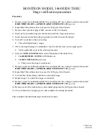


BONITRON MODEL 3460 RIDE THRU
Stage verification procedure
993003_20000629.doc
1 993003.doc
6/29/2000
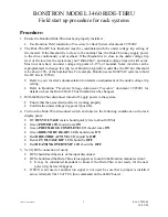
Procedure:
1. Remove power from Bonitron Ride Thru, and allow DC bus voltage to drain at least until
RIDE THRU READY
and
PRECHARGE COMPLETE
LEDs go out.
2. Open Ride Thru cabinet door to access the 3438 gate driver boards.
3. Remove the 4 pin male plug at TB1 on each of the 3438 boards.
4. Insert each 4 pin male plug into the female end of the "stage lockout rig".
5. Insert the male end of the lockout rig back into TB1 of each 3438 board.
6. Turn off 3 switches on the lockout rigs.
•
This will disable those 3 stages
7. After ensuring all plugs are reinstalled, close the cabinet door, and re-apply power.
•
Verify applicable steps of the start up procedure.
8. Press the
TEST SYSTEM
button on the front panel of the Ride Thru.
•
The
RIDE THRU ACTIVE
LED flashes on
•
The
BUS VOLTAGE
meter rises
•
This proves the stage is operational
9. Remove power from Bonitron Ride Thru, and allow DC bus voltage to drain at least until
RIDE THRU READY
and
PRECHARGE COMPLETE
LEDs go out.
10. Open Ride Thru cabinet door to access the 3438 gate driver boards.
11. Turn off the checked stage, and turn on one other stage.
12. Repeat steps 7-11 until all 4 stages are checked.
13. Remove power from Bonitron Ride Thru, and allow DC bus voltage to drain at least until
RIDE THRU READY
and
PRECHARGE COMPLETE
LEDs go out.
14. Remove each of the lockout rigs, and reinstall plugs into the 3438 gate driver boards.
15. Close cabinet door, reapply power, and complete the startup procedure.
This completes the individual stage checkout procedure.
Summary of Contents for M3460R
Page 11: ...990078_19990803 doc ...
Page 22: ...970066P_19991230 doc ...
Page 23: ...980265P_19991230 doc ...
Page 25: ...990256_19991022 doc ...
Page 27: ...000122_20000425 doc ...
Page 29: ...990036_19990827 doc ...
Page 30: ...970104_19991025 doc ...
Page 31: ...970103_19981028 doc ...
Page 32: ...990026_19991021 doc ...
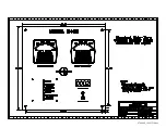
Page 33: ...990243_20000712 doc IGBT 150A 1200V IGBT 150A 1200V 150A 1200V IGBT 150A 1200V IGBT ...
Page 34: ...990244_20000712 doc ...
Page 35: ...980233_20000725 doc ...
Page 36: ...970200_20000718 doc ...
Page 37: ... SYSTEM NOTES ...