


Doc.# 985001
07/21/00
“THRESHOLD VOLTAGE” AND “LOW BUS SENSE”
ADJUSTMENT PROCEDURES FOR
MODEL M3460 RIDE-THRU MODULES
1. Overview
The "Threshold" voltage level is the voltage at which the Bonitron Model M3460 Ride-Thru module
maintains the DC bus during a power dip. Whenever the DC bus level drops to the "Threshold" setpoint, the
Ride-Thru module becomes active to regulate the DC bus voltage to the "Threshold" setpoint voltage.
The "Threshold" level is factory preset on all Bonitron Model M3460 Ride-Thru modules. These levels are
specified in the General Specifications section of the Customer Reference manual for each Ride-Thru
module. However, some field adjustment of this level may be required to achieve the optimum setpoint level
for any given system.
It is important to note that the Ride-Thru module’s "Low DC Bus" or "Output Under Voltage (OUV)"
setpoint is factory preset to 25V below the "Threshold" voltage. This setpoint should be maintained at 25V
below Threshold to avoid improper OUV fault activity.
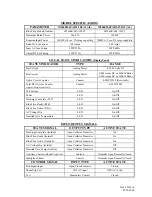
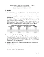
Table-1 below lists the typical factory setpoints for the "Threshold", "Low DC Bus (OUV)" and "Test Boost"
levels for the Model M3460 Ride-Thru modules based on the system AC or DC input voltage requirements.
Be sure to check the Customer Reference manual for each Ride-Thru module for specific setpoint levels.
Table-1: Factory Setpoints for Threshold and Test Boost Voltages
INPUT VOLTAGE
THRESHOLD
LOW DC BUS (OUV)
TEST BOOST
230VAC
290VDC
265VDC
+50VDC
370VDC
490VDC
465VDC
+75VDC
380VAC
490VDC
465VDC
+75VDC
400VAC
505VDC
480VDC
+100VDC
400VDC
595VDC
570VDC
+100VDC
415VAC
520VDC
495VDC
+100VDC
460VAC
590VDC
565VDC
+100VDC
2. Determining The Threshold Voltage Setpoint
Testing and adjustment of the "Threshold" voltage setpoint can be performed on systems in either an "On-line
and loaded" or an "Off-line and unloaded condition as described in methods 1 and 2 below. Each of the two
methods described require that you monitor the DC bus voltage during the testing and adjustment procedures.
Be sure to read through both adjustment methods completely before attempting any adjustment of the
"Threshold" and "Low DC Bus" voltage setpoints.
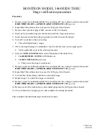
2.1 Method 1: Determining The Threshold Voltage Setpoint For An On-Line And
Loaded System
1) Verify proper installation.
Ensure that the Bonitron Model M3460 Ride-Thru module has been properly installed and wired according to
all applicable system and module wiring diagrams.
2) Push the "Test" button.
Push the "Test" button while monitoring the DC bus voltage.
Summary of Contents for M3460R
Page 11: ...990078_19990803 doc ...
Page 22: ...970066P_19991230 doc ...
Page 23: ...980265P_19991230 doc ...
Page 25: ...990256_19991022 doc ...
Page 27: ...000122_20000425 doc ...
Page 29: ...990036_19990827 doc ...
Page 30: ...970104_19991025 doc ...
Page 31: ...970103_19981028 doc ...
Page 32: ...990026_19991021 doc ...
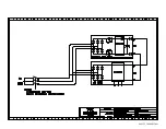
Page 33: ...990243_20000712 doc IGBT 150A 1200V IGBT 150A 1200V 150A 1200V IGBT 150A 1200V IGBT ...
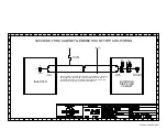
Page 34: ...990244_20000712 doc ...
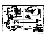
Page 35: ...980233_20000725 doc ...
Page 36: ...970200_20000718 doc ...
Page 37: ... SYSTEM NOTES ...