003002_20000112.doc
2 Doc.# 003002
01/12/00
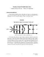
The faster the circuit is pulsed, the faster the energy is transferred to the load. The
'inductive boost' energy that is transferred to the load makes up the difference between
the input line voltage source, V
in
, and V
out
. The current at the moment of transfer is
equal to 'I
max
' and it will decrease at a rate of
(V
out
- V
in
)
/
L1
= Amps/Sec. If left long
enough, the current in the inductor will decrease to zero and D1 will become reverse
biased as the voltage across Q1 falls to V
in
. Depending on the load and the severity of
the dip, the Ride-Thru’s control circuitry sets the rate at which the energy transfer
occurs.
As you can visualize, up to 50% of your time may be spent filling your 'bucket'
with energy. Therefore, your 'bucket' of energy must be twice the size actually required
of the source. The Ride-Thru control circuitry uses multiple stages (more buckets) so
that energy can always be supplied to the load while some of the inductors are
recharging.
This process results in a much smoother primary and secondary load current and
can be expanded to as many stages as needed to reach a required KW rating. The
reason that paralleling is feasible is because each parallel circuit acts as a current
source entering the V
out
node voltage. An easy concept to grasp is that of a multiple
cylinder engine. For a given piston displacement, the greater the number of cylinders,
the more powerful the engine and the smoother the engine runs as long as an orderly
firing sequence is maintained. That is precisely what the Ride-Thru’s control circuitry
does. The 3460C1 control board can be used to stage up to four power circuits all
firing sequentially and out of phase with each other. These circuits can be cascaded to
higher numbers of sources, as power demands require.
The only field adjustment that is required for this circuit is the voltage at which
the circuit threshold is needed. The M3460R Ride-Thru will continue to provide
power to the load even for input voltage dips in excess of 50%, but at a reduced kW
rating.
Summary of Contents for M3460R
Page 11: ...990078_19990803 doc ...
Page 22: ...970066P_19991230 doc ...
Page 23: ...980265P_19991230 doc ...
Page 25: ...990256_19991022 doc ...
Page 27: ...000122_20000425 doc ...
Page 29: ...990036_19990827 doc ...
Page 30: ...970104_19991025 doc ...
Page 31: ...970103_19981028 doc ...
Page 32: ...990026_19991021 doc ...
Page 33: ...990243_20000712 doc IGBT 150A 1200V IGBT 150A 1200V 150A 1200V IGBT 150A 1200V IGBT ...
Page 34: ...990244_20000712 doc ...
Page 35: ...980233_20000725 doc ...
Page 36: ...970200_20000718 doc ...
Page 37: ... SYSTEM NOTES ...


