8.8“ Touchscreen Colour Display AHD 880 TC
Design and Function
V5
15
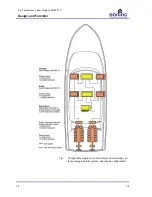
In addition, the system can be expanded with other components of
the AHD device family communicating via CAN-bus that can han-
dle numerous on board monitoring and control tasks. These sys-
tem data are also visualized on the AHD 880 TC display.
Among other things, the system can display the following ship
data:
Water and fuel tank levels
Trim tab angles and rudder position
Optimal trim tab angle at current cruising speed
Bilge alarms and pump status
Monitoring of doors and hatches, ladders, sea water cooled
exhaust gas systems and power supply systems
Condition of navigation lights
(requires Navigation Lights Monitoring System AHD-DPS 02)
Fuel consumption and range
(depending on the engine)
The connected sensors are monitored by one or several Data Sta-
tions AHD-SAS 15 (also incl. additional connected Data Station
AHD-PS-15, AHD-PS 30 or AHD-PS 47). All data are transmitted
to the display units via CAN-bus. Up to 15 sensors (current, power,
resistor, switch) can be led directly to the terminal strip of the Data
Station AHD-SAS 15.
The additional Data Stations AHD-PS 15, AHD-PS 30 or AHD-
PS 47 are current-controlled and can be connected via optocoupler
interfaces, increasing the possible sensor range by 15, 30, or 47
binary inputs.
The devices are provided with the project specific system configu-
ration at the factory. Generally, the system can be operated without
any further measures. Special configuration software makes it pos-
sible to adjust alarm texts or other parameters at a later point. Next
the alarm groups “Pre-Alarm” and “Main Alarm,” analogue sensors
can also be monitored for plausibility. A damaged sensor therefore
immediately triggers a sensor-error message.
Alarm notifications can be acknowledged directly at the display
from the touch screen or at the remote control via key press. How-
ever, the reason for alarm remains listed on the alarm page until its
cause has been resolved and normal values are pending at the in-
put.


